Using Thermohydraulic Simulations to Assess HRSG Performance

Posted on 10th Feb 2019

02/01/2019 | Jean-Mark M. Monnac

Thermohydraulic simulations can provide detailed heat recovery steam generator (HRSG) data to help determine the root cause of failures, predict the degree of wear from various mechanisms, and assess the overall thermal efficiency of the boilers. In this article, the results obtained from three case studies are presented to show the real-world benefits obtained through thermodynamic simulations.

Power plant staff needs reliable information on process conditions in heat recovery steam generators (HRSGs) to ensure safe operation and optimum performance. Current and historical operating data from the distributed control system (DCS) is a useful starting point, yet it does not provide detailed information on temperatures, pressures, or flows in all areas of the HRSG. This is achieved by running thermohydraulic simulations of the process. More detailed data can help in determining the root cause of failures or in predicting the degree of wear from a variety of mechanisms, including flow accelerated corrosion (FAC), fatigue, corrosion fatigue, and creep. Another advantage of simulation is that it can serve as a “test bed” to assess the impact of design or operating regime modifications on efficiency or unit life.

Three thermohydraulic HRSG simulations were performed using a commercial boiler simulation tool for real-life engineering assessments. The results are presented for the following case studies:

Software Description and Capabilities

A commercial thermohydraulic software—PowerPlantSimulator&Designer from KED GmbH—was used in these case studies. It allows the modeling of any type of boiler, such as biomass, conventional radiant boilers, HRSGs, or concentrated solar power stations. Each model is comprised of two distinct simulation components: the heat source (gas scheme) and the working fluid (water scheme).

The gas scheme is comprised of several elements that are typical for HRSGs in combined cycle plants. The process includes the following:

A typical gas scheme for a HRSG is shown in Figure 1.

1. A typical triple-pressure heat recovery steam generator (HRSG) gas scheme is shown here. The gas inlet from the gas turbine is on the left. The gas flows through the different tube bundles to the stack. Selected simulation output parameters are shown, including heat input, temperatures, and net electric output. Courtesy: Tetra Engineering Group Inc.

Once the gas scheme has been populated, the water scheme is setup to simulate the steam production and superheating. The process includes the following:

A typical water scheme for an HRSG is shown in Figure 2.

2. A typical triple-pressure HRSG water scheme is shown here. The water connections for each pressure level are colored for clarity: low pressure (yellow), intermediate pressure (green), and high pressure (blue). The superheated steam from each pressure level is duplicated to simulate the second HRSG and fed to steam turbine slices connected to a generator (bottom right). Courtesy: Tetra Engineering Group Inc.

All the input data is extracted from design documentation. Initially, the heat balance of the plant is used and the model is set to reflect the expected performance. Thereafter, operating data sent from the plant, usually taken from the DCS, is used to improve the model to better reflect the actual performance of the plant by taking degradation mechanisms such as fouling into consideration.

Increasing Thermal Efficiency: Approach Temperature Assessment

The following study assessed the impact on overall plant efficiency of lowering the LP economizer approach temperature in a triple-pressure HRSG.

The plant was comprised of two GTs providing flue gas to two triple-pressure HRSGs with reheat. The steam produced was fed to a single steam turbine. A recirculation system was present to keep the LP economizer water temperature greater than 55C to avoid cold-end condensation. The final approach temperature was controlled by a three-way valve that allowed bypassing the economizer to cool the water before it entered the drum.

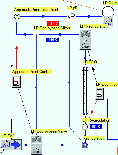
Approach temperature is the difference between the drum saturation temperature and the water entering the drum (or leaving the LP economizer). The general layout of this plant is shown in Figure 1 and Figure 2 for the gas and water schemes, respectively. More detail about the LP economizer configuration is shown in Figure 3.

3. This image shows the low-pressure economizer water scheme in more detail. The approach temperature is shown in the red box taken from the test point before entering the drum. In this iteration, the temperature was 154C, which corresponds to an approach point of 8C. Courtesy: Tetra Engineering Group Inc.

The HRSG simulation was set up as described previously. Once the inlet flue gas, heating surfaces, drums, and steam turbine were all input, the output was compared to guarantee design cases. Furthermore, DCS data from the plant was used for the final adjustments to ensure the simulation was as close as possible to actual operating conditions. At the time of the assessment, the plant was operating the HRSG with an 8C LP approach temperature. Three load cases were prepared corresponding to 100%, 75%, and 45% GT loads.

The main advantage of having an accurate simulation of a boiler or HRSG is that the impact of certain parameters can be investigated with no repercussions on pressure part or equipment integrity. In the context of this project, different test cases were run with approach temperatures ranging from the original 8C to 1C. The approach temperature of 0C was not considered as flashing upstream of the drum would occur. The emphasis of these test cases was to assess the impact on the integrity of the LP economizer, piping, and valves.

The main risks induced by lowering the approach temperature are the following:

    ■ Steaming in the economizer. If water evaporates in the economizer, this could lead to disruptions of the flow, deposit formation, vibrations, and flow stagnation, leading to tube-to-tube differential expansion.
    ■ Flashing to steam across the drum level control valve (LCV) and LP economizer recirculation valve, causing severe erosion through cavitation.

The material properties of all the susceptible components were reviewed and it was concluded that these would be able to withstand the increase in temperature.

Lowering the approach temperature allows the water entering the drum to be closer to saturation, and therefore, speeds its evaporation to steam. This means a lower evaporator circulation ratio (amount of circulation required for incoming saturated water to evaporate) in the drum is required, leading to an increased steam production. As expected, using an approach temperature of 1C or 2C led to the highest efficiency gain. However, industry practice is to keep the approach point greater than 3C to give more room for error regarding control instrumentation and operating uncertainty. Decreasing the approach temperature from 8C to 3C resulted in a 0.8 MW to 1.3 MW power increase, depending on the load case (Table 1).

Table 1. This table shows the power output and efficiency gain using a 3C approach point. Courtesy: Tetra Engineering Group Inc.

The simulation demonstrated that there are no major risks to component integrity when using an approach temperature of 3C and it was predicted that this would lead to an increase in power production of approximately 1.3 MW at 100% GT load. Assuming a price of $38/MWh (which was the average annual wholesale price of electricity in the U.S. in 2017, according to the U.S. Energy Information Administration) and 8,000 operating hours per year, a 1-MW increase would represent a net financial gain of $304,000 per year.

Above Selected Article is linked from below Website:

https://www.powermag.com/using-thermohydraulic-simulations-to-assess-hrsg-performance/

samgfg aliyu   comments at    2024-03-05 21:58:53
very interesting post. لعبة بادل

Leave a Comment