An inlet air cooling (IAC) system offers one of the most cost-effective ways to improve gas turbine (GT) performance—especially during the peak hours of hot summer months. After all, GT output depends on ambient air temperature—the higher the temperature, the lower the density, and the harder it is to move air mass through the GT. However, that’s not the only way IAC improves GT output. It also enhances compressor performance and enables more fuel to be ignited without increasing the firing temperature.
There are two major types of inlet air cooling: evaporative and chilling. Evaporative coolers and foggers fall in the first category; chillers and mechanical refrigeration make up the second. Evaporative cooling can cool the inlet air only to within one or two degrees of wet-bulb temperature, whereas chillers can cool to below dew point temperatures—in the 45F to 50F range.
Original equipment manufacturers (OEMs) have strict guidelines for cooling below this range due to icing concerns. As the air flow accelerates at the compressor inlet, it decreases the dynamic temperature by eight to 10 degrees, causing ice flakes to develop. At high velocities, the ice can cause serious blade damage and excessive vibration. Evaporative cooling systems require less capital investment and offer a shorter payback period, but they limit the potential gain in output.
Evaporative Cooling
In evaporative coolers, water is sprayed over the media and the latent heat of vaporization of water provides sensible cooling of the air. The quantity of evaporated water depends on the air’s ability to hold water vapor and is limited by the wet bulb temperature. In arid regions with low humidity, the potential gains are significant.
Many evaporative systems have mist eliminators downstream that capture water droplets to prevent carryover into the compressor. Foggers operate on the same principle: a fine mist of water droplets is sprayed in the air, but all the water is supplied for the sole purpose of evaporation with no water circulated back (Figure 1).
 |
| 1. Foggers. A pinless nozzle in a fogging system creates a fine mist of water droplets for the sole purpose of evaporation. Courtesy: NAES Corp. |
The design of the fogging system, including the selection of pumps, is important. The placement of fogging nozzle arrays is critical in determining the residence time for evaporation. Residence time is primarily a function of droplet size, and dry-bulb and wet-bulb temperatures. It’s essential that all of the droplets evaporate before they reach the compressor inlet to prevent water carryover.
Some droplets will agglomerate and condense on the walls, silencers, and other obstructions, so it’s important to provide drains. The system should be designed to minimize wastage of water. Nozzle arrays, and the location of nozzles within the arrays, must be positioned to provide uniform coverage in a wide variety of operating conditions.
Chilling
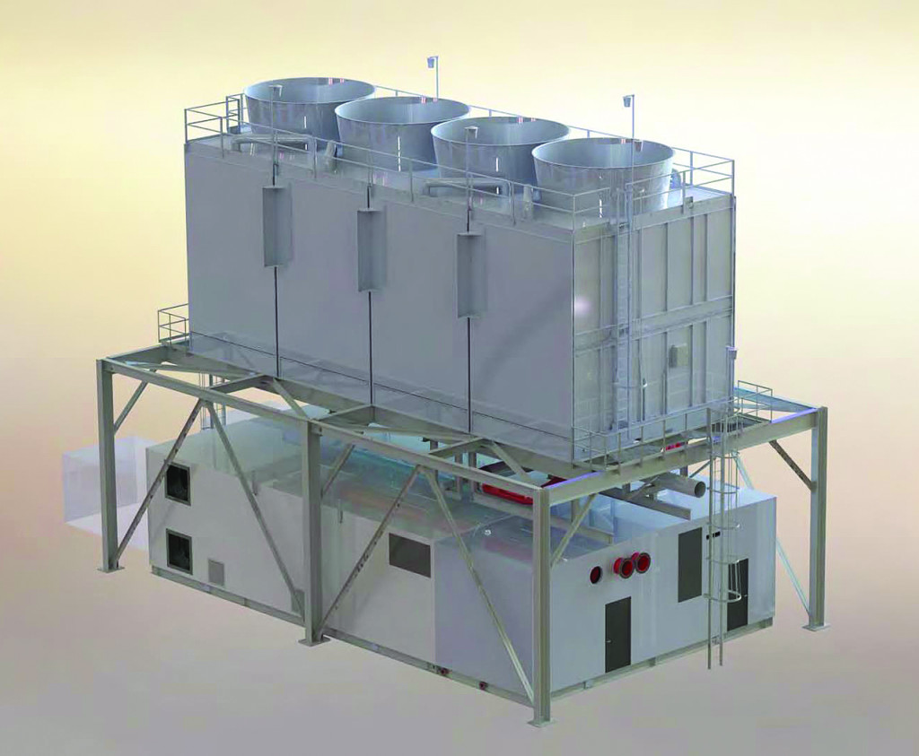
With mechanical chilling (Figure 2), the inlet air can be cooled to below dew point temperatures, achieving a more consistent and dependable compressor inlet air temperature. Because this process involves removing water vapor from the air, it can add a significant auxiliary load—even more so in regions with higher humidity during the summer months. On average, the auxiliary load equals about a third of the output gain. Depending on whether the plant is simple or combined cycle, this may impact the heat rate.
 |
| 2. Chillers. The chiller package shown here is a typical design for common gas turbines. Courtesy: NAES Corp. |
Chillers typically run on electric power, although there are also absorption chillers that operate on steam, hot water, or natural gas. Absorbers have a low coefficient of performance (COP)—in the range of 0.7 to 1.2—depending on whether they are single- or double-effect. Electrically driven chillers, on the other hand, have a COP of 3 or higher, so absorbers are justified only when there is excess steam or hot water available that cannot be used for other purposes. If steam is pulled from the steam turbine to operate them, it can negatively impact the heat rate.
If the objective is to increase output for a few hours per day, chilling can be combined with thermal storage to accomplish this during peak periods. With thermal storage, the cold reservoir is built during off-peak hours, and the chilled water is used during peak hours to provide cooling. Since the chillers may not be running at all—or only at partial load during peak hours—the output is optimized during peak hours when it is needed most. However, thermal storage designs are site-specific and require detailed evaluations to maximize the benefit.
Wet Compression
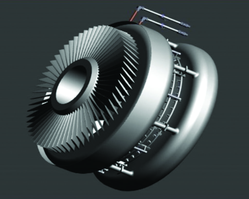
In addition to evaporative cooling and chilling, there is another class of inlet air cooling known as wet compression or high fogging, depending on the OEM (Figure 3). With wet compression, water droplets are introduced in excess of what is required for evaporative cooling—with the intention of producing carryover to the compressor. The work of compression raises the air temperature, which in turn increases its capacity to absorb water. The excess water carried over into the compressor is thus absorbed in the successive compressor stages.
 |
| 3. Good carryover. Wet compression nozzles introduce water droplets that enter the compressor, where higher air temperatures resulting from work of compression absorb the liquid. Courtesy: NAES Corp. |
The compressor stage in which full evaporation takes place depends on the quantity of water injected. The compressor consumes about half to two-thirds of the power produced by the gas turbine, so any reduction in its power consumption corresponds to higher net power output. Because it takes less energy to compress cooler air, the compressor draws less power, increasing the turbine’s net output. This also reduces the compressor’s discharge temperature, allowing more fuel to be fired in the combustor while maintaining the same firing temperature. The increased mass flow, improvement in compressor efficiency, and ability to fire harder without raising firing temperature cumulatively produce more power.
Wet compressor injection flow rates are typically expressed as a percentage of air intake—usually from 0.5% to 2%. It’s rare that this value is allowed to go higher. For example, the suggested low-pressure compressor flow rate for one OEM’s 50-MW GT is less than 1% of airflow.
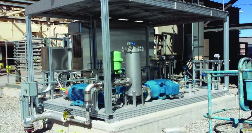
Of all the cooling system options, wet compression requires the most caution, because the nozzles are placed close to the compressor inlet. It’s important to minimize the risk of any part becoming loose and carrying over into the compressor. Wet compression is sometimes used in combination with either evaporative cooling or chilling to further enhance performance (Figure 4).
 |
| 4. Tools of the trade. The skid shown here includes the equipment needed for one plant’s fogging and wet compression inlet air cooling system. Courtesy: NAES Corp. |
—Sanjeev Jolly, PE is senior engineer, Engineering Services, for NAES Corp.
https://www.powermag.com/inlet-air-cooling-systems-improve-gas-turbine-performance/