Losses attributed to condenser tube leaks, fouling, and failures continue to climb, costing the power generation industry an estimated half-billion dollars annually in maintenance costs and loss of production. Investing in an effective condenser maintenance program will reduce those expenses in short order.
Maintaining clean condenser tubes is of vital importance to reliable, efficient power plant operation. Condenser tubes may become lightly fouled with soft organic deposits or severely scaled with hardened minerals that are difficult to remove. Success in cleaning the condenser requires selecting the appropriate cleaning technology for the specific fouling conditions.
Early identification of fouling characteristics and a fundamental knowledge of cleaning system capabilities are essential to determining the most effective cleaning technology, as well as the frequency of cleaning required. A good engineered coating can also prevent fouling of condenser tubes and renew life in older systems.
Mechanisms of Condenser Tube Fouling
Generally, two major problems result from substances that adhere to interior tube surfaces: loss of heat transfer and under-deposit corrosion.
Internal tube fouling is nearly always detrimental to heat transfer because it reduces the efficiency of condensing steam and results in less-efficient steam turbine operation, as discussed in detail in the previous article, “Optimizing Condenser Tube Selection.” Internal tube fouling is also the most common cause of under-deposit corrosion–related tube failure.
This form of corrosion can be caused either directly or indirectly. When the attack is direct, the deposit itself contains corrosive substances which, when concentrated at a localized site, can cause loss of tube material. A common example of this type of corrosion would be chloride pitting. Indirect attacks can be caused by several factors, including accumulation of deposits that form a barrier between the cooling water and tube material, allowing a corrosion cell to form underneath, or by microbiologically influenced corrosion (MIC). Pitting is often a result, which can cause tube failure well before the material’s life expectancy.
In either situation, contaminants in cooling water (which may be concentrated significantly in a recirculating cooling tower) are the precursors to what often results in major damage to boiler tubing and steam turbine materials, potentially resulting in huge economic penalties in unit outages and equipment repair and/or replacement. Investment in the equipment that can remove and/or prevent foulants from forming on condenser tubes is a minor price to pay to produce the best possible plant economics.
Options for Preventing and Removing Foulants
Equipment options for preventing and/or removing foulants can be classified according to plant operating status: off-line or online. Off-line removal methods include chemical (acid or chelate dissolution) and mechanical methods (metal or plastic tube cleaners, brushes, high-pressure water, and the like). Online preventive measures include chemical treatments (scale and corrosion inhibition, dispersants, and biocides) and continuous recirculation of sponge balls to remove soft deposits on the inner wall of the condenser tubes.
Because condenser fouling can have such a dramatic impact on cost-effective power plant operation, deposition and corrosion should be carefully monitored and the appropriate cleaning technology used at optimal intervals. Here is an overview of the main treatment options.
Chemical Treatment Methods. Several chemicals, often in combination, are used to control condenser tube fouling. Chemicals are primarily utilized with recirculating cooling towers, because the concentration of dissolved constituents is significant, increasing the threat of scaling and corrosion, and because once-through cooling systems often discharge directly into a river or lake, so chemicals are restricted in the effluent. Typical chemical treatment methods used today include adding scale inhibitors, dispersants, biocides, corrosion inhibitors, and chemicals for pH control.
Another common way of mitigating chemically influenced problems is to minimize the concentration of dissolved solids in the system, particularly in cooling towers. A balance must be achieved between minimizing water use and avoiding excessive buildup of scaling and corrosive constituents in recirculated water.
Some scales can be removed online by lowering circulating water pH to the point of scale dissolution by increasing the sulfuric acid feed (pH of 5.8 or less for calcium carbonate and 4.0 for calcium phosphate). However, potential risks to base metal and carbon steel piping must be carefully considered when using such harsh chemicals. In the case of online chemical cleaning by pH reduction, one major disadvantage is that you can’t be sure of the composition of the foulants.
Chemical scale removal can be very effective and may be necessary if the deposits are silica-based. However, chemical cleaning of condensers is maintenance- and labor-intensive.
Mechanical Fouling Prevention. A number of mechanical approaches have been developed to prevent condenser tube fouling. Screens can be installed to block large debris from reaching the condenser while settling ponds and/or clarifiers remove particulate and some dissolved constituents. Filtration systems, such as sand filters, can also be employed to remove fine particulates, on either a full-flow or a side stream partial-flow basis.
A number of online systems have been developed that send cleaning objects—such as sponge balls, brushes, or plastic scrapers—through tubes with the cooling water flow. In theory, these devices will mechanically wipe the tube surface clean. In the more automated systems, the cleaning devices are retrieved at the condenser outlet and automatically returned to the inlet. Other designs return the devices to the inlet via backwashing. Because of the random distribution of some of the cleaning devices, not all tubes receive consistent cleaning.
Increasing cooling water flow through the condenser can be effective in limiting microbiological growth. This approach will also keep cooling water temperatures lower, possibly to a point at which scale is less likely to form. However, higher flow rates can cause increased rates of erosion-corrosion in copper alloys.
Mechanical Removal Methods. Plant operating economics favor removing any deposits before they cause major loss of heat transfer, tube corrosion, or, ultimately, tube failure. Not only are there losses in performance to consider, but major equipment repairs often follow tube failures due to cooling water contaminants in the boiler or turbine. In general, mechanical cleaning is usually more cost-effective than chemical cleaning.
Mechanical cleaning techniques include high-pressure water washing and shooting tube cleaners (Figure 1) through the tubes. When balancing the need for clean condenser tubes against the time required for cleaning, mechanical tube cleaners are an excellent choice. High-pressure water washing can be very time-consuming, but using tube cleaner brushes for removing soft deposits or metal tube cleaners for more difficult deposits can be a quicker solution.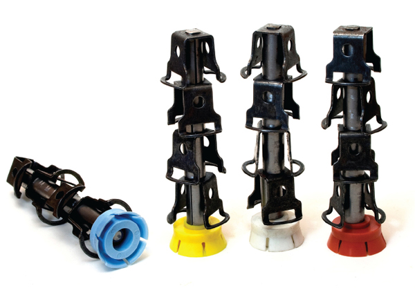
1. Mechanical tube cleaner. Source: Conco Systems Inc.
Off-line mechanical tube cleaners have been a reliable and effective technology since their introduction by Conco Systems Inc. in 1923. Tube cleaner designs are continually evolving to meet the needs of various fouling situations, and offline types of tube cleaners have distinct advantages over other tube cleaning methods in many scenarios. The most effective metal tube cleaners are engineered to closely match tube interior dimensions in order to clean near to the base metal.
The industry’s standard mechanical cleaners are propelled through the tubing at high velocity (20 ft/sec) by pressurized water (see Figure 1). Occasionally, when difficult deposits and corrosion products are encountered, repeated passes of the tube cleaners may be needed to ensure optimal cleaning.
The common procedure for this cleaning process is for workers to insert the tube cleaners in one section of the tube sheet at an inlet waterbox and then, using pressurized water, shoot the cleaners through to the outlet water box (Figure 2). Those cleaners that are still in good shape are reused, while old cleaners are discarded. Typically, metal tube cleaners can be used up to 12 times before they become ineffective. Even with large condensers, cleaning may take only several days and can easily be incorporated into a scheduled outage or period of reduced load.
2. Tube cleaner in action. Source: Conco Systems Inc.
Condenser Tube Maintenance: Assessment
Preventing condenser tube failures is vital for plant reliability. Even a single condenser tube leak can bring a unit off-line; the costs for lost generation, labor to repair the leak, and unit startup can easily exceed several million dollars. Thus, preventive techniques, including tube condition assessment, leak detection, and plugging leaking tubes can save considerable money.
Luckily, we now have devices that can quickly determine tube wall thickness. This data provides direct information about tube integrity and projected life expectancy. A popular and effective method for these determinations is eddy current testing (ECT). ECT utilizes electromagnetic induction to evaluate tube walls for imperfections and thickness. Figure 3 shows an ECT probe and the magnetic field created. A uniform wall will give a steady reading, but pitting, corrosion, through-wall penetrations, cracks, or wall thinning will be detected and the location of the imperfection reported by the ECT.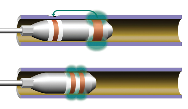
3. ECT probe and magnetic field. Courtesy: Zetec Inc.
ECT data collection speed is dependent upon tube length and material as well as the type of defects expected. Typically, partial ECT is used to evaluate overall condenser condition and will be performed perhaps on every 10th tube or on some percentage—such as 10%, 20%, or 50%—of the tubes in a condenser. On the other hand, 100% testing is intended to identify and plug tubes that have the potential for leaking and causing unit outages.
If a particular section of the condenser has suffered from abnormally high tube failures, the ECT testers can focus on that section, if necessary. For example, the air removal section of a condenser concentrates oxygen and ammonia from treatment chemicals. This is a section known for a high failure rate of condenser tubes. Other locations of common corrosion include tubes directly impinged by steam flow, fretting locations at tube support plates, the area directly below the air removal section, and tubes near the entry of process fluids, such as feedwater heater drips.
When the analysis of data gathered with ECT is evaluated, tube-plugging criteria can be established based on defect parameters. By proactively taking action on questionable tubes, operators can dramatically reduce the likelihood of a tube failure within their condenser’s normal life expectancy. The analysis report generated typically includes a color-coded tubesheet map for easy identification of the problem areas, such as the example shown in Figure 4. Selected tubes are then plugged.
4. Color-coded tubesheet map. Courtesy: Conco Systems Inc.
For ECT to be successful, effective tube cleaning must first be performed. The ECT probes must be able to obtain a fill factor of greater than 80% and preferably 85% to be accurate. Should tube deposits be left behind, they could cause erroneous readings or mask problem areas. The preventive maintenance costs of ECT may easily outweigh the costs related to a single tube failure.
Condenser Tube Maintenance: Leak Detection
Air that enters condensers, unless properly removed, will coat condenser tubes and restrict heat transfer, just as waterside tube deposits do. Air in-leakage will also introduce oxygen to the condensate, and this oxygen may cause corrosion of downstream condensate/feedwater piping and feedwater heater components.
All condensers are equipped with at least one air-removal section, which consists of a compartment that runs the length of the condenser and is only open in one area, typically at the bottom. A vacuum is applied to this compartment to remove noncondensable gases that enter the system, primarily air from in-leakage. At start-up, the vacuum may be applied by a steam jet air ejector, but normal vacuum is applied by electrically driven pumps.
The strong vacuum that collapsing steam generates in a condenser will pull in air from many locations. Some of the most common include piping penetrations into the condenser, turbine-condenser expansion joints, and turbine rupture diaphragms. Alternatively, a failure of an air removal pump may allow excess air to accumulate in the condenser. Regardless of the failure mechanism, unless the leak is very small, it can be extremely valuable to have a leak detection contractor come in and locate the sources so that they can be repaired. Tracer gas testing can be used to track down the leak.
Plant maintenance specialists are usually aware that points of excess air in-leakage to a condenser can often be discovered by use of a tracer gas such as helium or sulfur hexafluoride (SF 6). A monitor is placed at the exhaust of a condenser air removal pump, and then trained personnel move methodically around the condenser and auxiliary equipment spraying small quantities of the tracer gas at potential in-leakage points. Unlike helium, SF 6can be injected below the water line in a running water box to quickly determine if that water box has the leaking bundle.
Another notable difference between the two tracer gases is their level of sensitivity. The lowest detection limit for helium is approximately one part-per-million above background level, thus making detection sometimes difficult or impossible for small leaks. SF 6, on the other hand, can be detected at a concentration of 0.01 part per billion; consequently, it provides much better results.
The tracer gas method is relatively straightforward. One technician at the monitor observes tracings on a strip chart recorder while technicians in the water box (Figure 5) place a series of increasingly smaller plenums over a section of the tubesheet to zero in on the failed tube. Once each section is in place, a technician injects the tracer gas and notifies the monitor technician via two-way radio; this system allows staff to quickly communicate and find the failed tube efficiently. A typical response time between gas injection and readout at the analyzer is 30 to 45 seconds.
5. A technician holds a plenum during tracer gas condenser tube testing. Courtesy: Conco Systems Inc.
Condenser Tube Maintenance: Plugging
If ECT results indicate a leak, or a condenser tube leak or failure occurs, the tube must be plugged, so you must have the right tube plugs on hand. It is recommended to have a ready supply of correctly sized tube plugs for the condenser and various heat exchangers in stock and ready for use. A good rule of thumb is to maintain enough plugs equal to 2% of your tube quantity. A 10,000-tube condenser requires a minimum stock of 200 plugs.
In addition to plugging new leaks, existing plugs should inspected and replaced regularly. Both ends of the tube should be properly cleaned and dried. Both ends of the tube must be plugged, according to the manufacturer recommendations, and their locations marked on a tube sheet map. Figure 6 shows a cross section of a highly reliable tube plug.
6. Cross section of a tube plug. Courtesy: Conco Systems Inc.
Coatings Can Extend Condenser Life
Coatings have been an important element of maintaining the integrity and even extending the life of steam condensers. Although coatings are generally thought of in terms of protecting metal surfaces from erosion and corrosion, they can serve the equally important purpose of sealing small leaks and preventing pits from growing into a leak. Raw water intrusion associated with tube-to-tubesheet joints, waterbox-to-shell joints, and even the tubes themselves can be coated. Air intrusion through the waterbox-to-shell joint can also be stopped with the proper application of the right coating.
Coatings for the condenser usually fall into five basic categories: tubesheet coating, tube-end inner-diameter (ID) coating, waterbox and circulating water piping/tunnels coating, exterior flange sealing, and full-length ID tube coating.
Tubesheet Coating. A leak-tight joint between tube and tubesheet is critical to the proper operation of steam surface condensers and other heat exchange equipment. Loss of tube-to-tubesheet joint integrity can be normally traced to three root causes: corrosion and/or erosion of the tubesheet material, improper rolling of the tubes during installation, or mechanical stresses during operation.
Tubesheet corrosion is typically caused by dissimilarities with higher-alloy, more-noble tube material. This situation is becoming more and more prevalent as high-performance stainless steel and titanium tubes are being retrofitted into older condensers and heat exchangers. Loss of tubesheet metal due to corrosion leads to compromised tube-to-tubesheet joint integrity. The options for tubesheet protection are typically cathodic protection or the use of coatings.
Cathodic protection of tubesheets can be difficult due to variations in water quality, turbulence, and the inability to space anodes and reference cells effectively. Another problem is that cathodic protection system maintenance is often overlooked by plant staff.
Coatings are ideal, as they passively protect these surfaces. However, if a spot failure of the coating occurs on a tubesheet with dissimilar tube material, the galvanic cell can be concentrated in a small area, leading to rapid loss of metal. Figure 7 shows an aluminum bronze tubesheet with titanium tubes in salt water where a thin tubesheet coating had spot failures. Galvanic corrosion caused a rapid loss of tube joint integrity at that spot.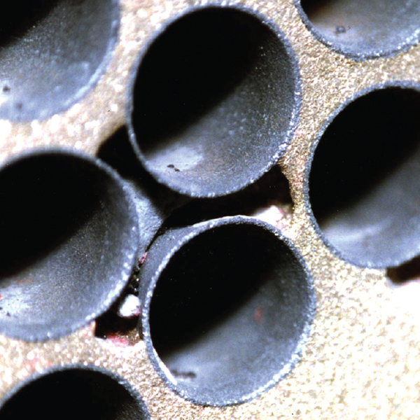
7. Galvanic attack at point of thin-film coating failure. Courtesy: Plastocor Inc.
The tubesheet and tubes are completely encapsulated and locked in by a thick, flat, layer of 180 ±40 mil epoxy. This process fashions a radial-flared, high-gloss inlet and outlet tube opening, serving to dramatically reduce flow resistance and fouling. The flat and smooth surface allows for easier leak detection and reduces sponge ball wear if an online tube-cleaning system is used. The substantial nature of the system adds strength and integrity to the tube-to-tubesheet joint. Tube push-out strength is increased by 2,000 pounds by the adhesive value of the coating system.
Tubesheet coating can be applied to any tube-to-tubesheet configuration experiencing any level of deterioration, provided that structural integrity is not threatened. The epoxy coating is engineered to withstand physical abuse, impact, and other physical/chemical stresses associated with the operation of a cooling water system. Figure 8 shows this thick cladding on a tubesheet after 15 years in service.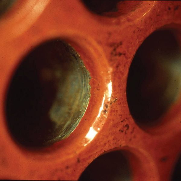
8. Thick epoxy tubesheet cladding after 15 years service. Courtesy: Plastocor Inc.
Tube-end ID Coating. Copper-based tube alloys can be subject to selective erosion within the first several tube diameters of the inlet tube end. Other tube materials can deteriorate because of galvanic or microbiological issues.
Inlet-end erosion is due to turbulence present at the initial section of tube before laminar flow is established. The degree of erosion depends on the nature and amount of entrained solids in the cooling water, the type of tube alloy and its susceptibility to corrosion, water velocities, micro/macrofouling of tube surfaces, and other design/operating factors. Outlet-end erosion may also occur due to outlet flow–induced turbulences or cavitation.
The tube-end IDs can be selectively coated to protect this specific area of the tube. In this case, three coats of alternating colors are applied to provide complete protection. The epoxy coating can be installed to any depth and is applied in conjunction with the tubesheet coating. Each coat is approximately 2 to 3 mils thick and is applied just past the previous coat. This three-stage method creates a feathered termination, eliminating the chance of step-erosion at the end of the coating.
This method of application also can bridge small perforations of the tube wall, thereby repairing the tube and speeding up its return to service. The joining of the tubesheet coating with the inlet coating creates a uniform and smooth transition from waterbox chamber to tube interior. This reduces fouling and turbulence, which raises flow efficiencies. The tube ID is not significantly reduced, which permits the unrestricted use of ECT and most tube-cleaning methods.
Figure 9 shows a cross-section schematic of the tube-end ID coating along with the tubesheet coating. If the tube ends are thinned to the point where structural integrity is threatened, then a metallic insert can be incorporated into the system. Here, the insert is precisely sized and glued in place.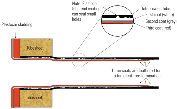
9. Tube-end ID coating with tubesheet epoxy coating. Courtesy: Plastocor Inc.
Waterboxes, Piping, and Tunnels. Condenser waterboxes and circulating water piping/tunnels are also routinely coated. In these applications, the coating system usually consists of an epoxy liner installed from 40 to 125 mils in thickness. The thicker applications are used when corroded surfaces are coated or where a “bullet proof” lining is required.
Exterior Flange Sealing. Air in-leakage into the steam side of condensers has far-reaching consequences for plant efficiency and equipment life. High levels of dissolved O 2 elevate corrosion in the feedwater heater train, boiler, and steam generator systems. Corrosion contributes to poor heat transfer and threatens system integrity. Air binding and incomplete removal of the noncondensables can result, causing excessive corrosion to the tubes outside of the air removal zone. Tubes and surfaces in this region of the condenser are excellent candidates for an engineered coating.
Furthermore, the gasket between the waterbox and tubesheet can start to break down due to embrittlement over time. Hydrodynamic stresses from waterbox loading and possible startup water hammer further aggravate gasket integrity. Differential thermal stresses resulting from steam dumps, plant trips, and the like compound the problem. Air in-leakage around the gasket, through the bolt holes, and into the condenser shell is the result. Leak paths can be elusive, as various sealing materials may have been applied over old repairs, which can result in an ineffective buildup of various paints, anti-sweat coatings, caulks, and other compounds around the external condenser flange. This flange area is another good candidate for an epoxy coating.
Plastocor Inc. has developed a methodology whereby these old materials are completely removed and a new sealing system is installed, completely eliminating air in-leakage from the waterbox-to-tubesheet flange area.
These methods can be applied to almost any other areas in the system where air intrudes. For the external joint, these methods can be employed while the unit is either online or off-line. The sealing system can be installed as the previous materials are removed so severe leaks can be resealed as they are uncovered. Online applications should be done in conjunction with leak detection surveillance.
The system is equally effective when applied on the inside of the waterbox to stop cooling water in-leakage or air in-leakage in situations where the waterboxes are not completely flooded.
Full-Length Tube ID Coating. The tubes used in steam condensers and other balance-of-plant heat exchangers are selected so that they will provide decades of reliable service. Often, tubes may begin to develop pits, which, if not mitigated or otherwise controlled, can result in tube leaks. In most cases, the tube must then be identified and plugged. Significant costs are incurred locating and plugging a tube, all because of a single pit.
When a pit is identified, the plant typically chooses one or more of the following actions: improve tube cleanliness, chemically treat the tubes, and/or use ECT and preventative plugging. Ultimately, when many tube losses occur, a condenser retubing is necessary.
A fourth option is to coat the tube ID with an epoxy coating. Though it is common to coat carbon steel tubes in the process industry, tube coating in the power industry has been slow to gain acceptance. The primary reason for this is that power plant heat exchange bundles are less abundant than process industry bundles and are not routinely removed for service; main steam condensers are fixed structures and cannot be removed for off-line shop maintenance. Full-length tube coatings are also difficult to apply properly in the field, particularly under outage time constraints. Furthermore, concerns exist about the heat transfer effects of the coating and its life expectancy.
The aim of an epoxy coating is to target and fill (remediate) existing pits and apply a uniform but minimal film in one coat over the unpitted surface of the tube to minimize heat transfer loss while offering protection. If a tube is made of a resistant alloy (not carbon steel), areas that are not pitted do not need a thick film coating for protection. A minimal film will provide sufficient protection while not overly affecting heat transfer. This coating film can even be engineered to provide additional benefits, such as fouling resistance.
Coat Inside the Tube. A new approach to applying coatings has been developed that addresses the concerns noted above. Instead of using a spray head to disperse the coating throughout the tube, a pigging technology was developed whereby a “slug” of coating is introduced into one end of the tube and a specially designed and sized coating pig is propelled down its length with compressed air or drawn down the tube with a rod or line. The pig pushes the “slug” of coating along the tube, causing it to enter and fill the pits as it travels through the tube. The pig is designed to remove, or squeegee off, as much coating as possible as it travels through the tube. The result is that the pits are filled with coating while the tube interior in general is left with a very thin film of coating. Coating thickness on the tube wall is commonly less than 1 mil. The elements of this “squeegee pig” approach are shown in Figure 10.
10. Schematic (enlarged) of pitted tube and squeegee pig in the process of coating the interior of a tube. Source: Plastocor Inc.
In the case where there are known holes in the tube, the coating system is modified so that the pig is pulled through the tube with a line. This eliminates the pressure differential created when compressed air is used.
In one plant, a condenser with brass tubes developed serious pitting problems and holes. The tubes were coated using the technique just described. Figure 11 shows the inside of the tube before and after application of the coating. The hole has been sealed, the pits filled, and there is a thin translucent coating of epoxy on the rest of the tube wall.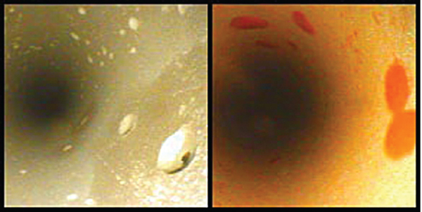
11. Videoscope image of the interior of an admiralty brass tube with holes and other defects before (left) and after (right) coating. Source: Plastocor Inc.
This technique is providing another tool to maintain and extend the lifespan of condensers. In addition to stopping further deterioration, a properly applied epoxy coating can extend the operating life of the condenser internals and defer the cost of an expensive condenser retubing.
— Eric H. Fayard (eric@concosystems.net) is technical marketing manager for Conco Systems Inc. Michael J. Horn (mike@plastocor.com) is president of Plastocor Inc.
https://www.powermag.com/improving-condenser-om-practices/?pagenum=1