Many power plants have sediment retention ponds that require control of pH for the effluent. The following guidelines for fossil plant sediment pond pH control will help you design a robust system while staying within budget.
Sources of influent arrive in power plant retention ponds from coal yard run-off, demineralizer room operations, air heater cleaning, and other plant locations. All of those sources are usually acidic. The challenge for plant operators is to quickly and accurately correct the pH of the effluent to an acceptable pH as additional acidic flows enter the pond.
Previous control strategies were quick and crude in nature, likely due to assumptions that a traditional proportional-integral (PI) controller should keep effluent pH to the setpoint. In practice, however, this is not the case.
Typically, power plants have used a pneumatic controller with a single valve to add reagent to the influent stream for the purpose of controlling effluent pH (Figure 1). Little thought was given to the process requirements for this type of control. Some operational practices included using existing on-site water tanks in an attempt to perform batch-type pre-treatment. This sort of manual operation would only result in having pH “jump” repeatedly from below 2 to above 9.
 |
| 1. Single-valve pneumatic controller. Typical as-found sediment pond pH control. Source: NRG Energy |
This scenario is unacceptable due to possible uncontrolled chemical reaction and inefficient use of chemicals. The objective is to rectify the control situation—within tight budget constraints. To aid other power plants in reaching that goal, this article addresses four design considerations developed as part of sediment pond pH control projects recently completed at two NRG Energy plants: correct pH measurement, reagent delivery/injection that minimizes dead time and provides exact reagent charge, mixing of the reagent into the influent flow completely, and properly designing the pH controller so that it can function with a nonlinear process (pH titration curve).
Correct pH Measurement
Correct pH measurement is self-explanatory. For a feedback control system to function properly, there must be a valid process measurement. Measurement error and measurement dead time also can cause undesirable results. It is imperative that the responsible group maintain the pH measuring cell by cleaning it, checking calibration, and verifying response time on a periodic basis that particular conditions require.
Reagent Delivery and Injection
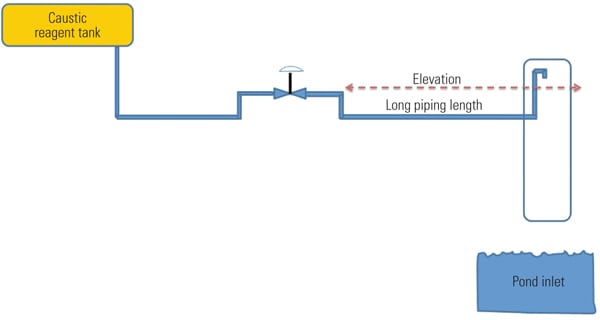
Due to the relatively high freezing point of the caustic solution, long reagent delivery piping was buried underground, with the control valves installed at a higher elevation in heated buildings (Figure 2). However, minimizing reagent delivery time to the influent is very important. At one end of the spectrum is a delivery dead-time goal of zero, but that is not easily attainable. At the other end are actual findings of dead-time delays up to 2 minutes. Step-change tests illustrated typical dead times of over 1 minute. These results have a similar effect to reset wind-up with a “sticking” valve that continuously sticks and then becomes unstuck.
 |
| 2. Higher ground. Typical as-found piping arrangement. Source: NRG Energy |
There is no effective way to tune out this dead time in a pneumatic controller, because dead time depends more on physical piping than on the control system tuning. Dead time varies from what takes place, in time, before. That is, if the reagent pipe is flowing and the valve shuts and then immediately re-opens, dead time decreases. However, if the valve is shut for a long time and reagent piping is drained, then there is a long dead time due to the pipe refilling.
A cost-effective approach to reducing dead time is to install little additional pipe. At the delivery point, pipe is added in the vertical direction such that the end is higher than the control valve position on the horizontal plane (Figure 3). Depending on the physical area, a minimal amount of heat tracing may need to be installed. In some instances a large-diameter pipe or other protective barrier can be affixed over the injection point should wind and/or personnel safety be a concern. The barrier pipe diameter is large enough to ensure no reagent contacts it. The new layout prevents draining and refilling issues and dramatically reduces process dead time.
 |
| 3. Delivery point. Reagent delivery piping modifications. Source: NRG Energy |
Efficient Mixing of the Reagent
Uniform mixing of the reagent into the inlet stream of the pond is essential to obtaining acceptable pH measurement. Consideration is given to highest inlet flow potential to ensure the mixing apparatus effectively provides a near-homogeneous solution for the control measurement pH cell.
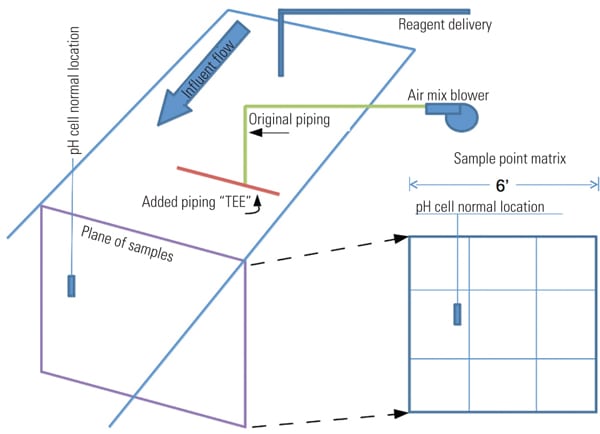
In one project, the “as found” installed mixing system was an air blower with a single pipe submerged in the inlet stream. An imaginary matrix plane placed perpendicular to the flow through the inlet trough was used to locate the measurement cell during pH tests to determine mixing effectiveness (Figure 4). Each section measurement is obtained by using a portable pH meter. With a constant inlet flow and a locked control valve, tests indicated considerable pH variation across the measurement plane.
 |
| 4. Test plane matrix. An imaginary matrix plane in the inlet trough across the point where the measurement cell is located is utilized for testing. Source: NRG Energy |
Minor changes to the air blower piping improved the mixing results. Piping was teed under the water level and moved close to the bottom of the trough. The ends of the tee were positioned approximately one-third and two-thirds of the distance across the trough.
Design of a pH Controller
Sediment pond influent is made up of many converging sources. Demineralizer effluent triggered by regeneration of deionizing beds is one major pH control difficulty. This effluent has sulfuric acid as a prevalent component. The reagent used for the control of acidic influent to a pond is caustic soda, which is diluted to approximately 20% by weight. The lowest observed sediment pond inlet pH value is 1.4. The limits of the outfall pH value are 6.0 and 9.0. Control “soft” limit goals are 6.5 and 8.0. Note that tuning this control system loop is performed for system loading upset, as setpoint changes are either minimal or not utilized.
PI controllers have limitations in working with nonlinear processes, though a certain amount of robustness can be tuned in. There is a tradeoff, however. The controller that is tuned to maintain minimum error is not robust for changes in the system or process. The controller that is tuned to be overly robust will be too sluggish at many points of control to be considered effective.
System nonlinearity results from three factors: the end-element, control-valve characteristic; head pressure change, as the reagent is gravity fed from a diluted caustic storage tank with a level that is not automatically maintained; and the nature of pH itself.
The accepted practice is to linearize any control loop such that tuning settings of the controller produce acceptable results by minimizing error from the setpoint—by being robust and by being able to perform well over the entire system load range. If the end element is the cause of the nonlinearity, then that is where the characterization should take place. If the measurement has nonlinearity, then the characterization should take place on the measurement. As a result, characterization of the input, output, or both is dependent on which areas are developing the nonlinearity.
However, in the case of pH control, the process itself is nonlinear, and this nonlinear nature presents a major challenge for the series PI controller. The gain of the process is represented by the pH titration curve. Figure 5 is an actual titration curve from a plant site. Notice the caustic solution was found to be 21.1%. This illustrates that the reagent solution is another variable, as the plant dilutes the delivered 50% caustic soda, so minor variances can be expected.
 |
| 5. Plant titration curve. The caustic solution at one plant was found to be 21.1%, illustrating that the reagent solution is another variable, as the plant dilutes the delivered 50% caustic soda. Note that the titration curve represents very high process gain near the setpoint of 7.0 and very low process gain at low pH measurement. The shape of the titration curve suggests that a multifunction controller is required. Source: NRG Energy |
The “S” shape of the curve represents gain change of the process that the controller must handle. Actual measured low pH inlet value to the pond inlet is 1.4. To illustrate this further, consider the following examples:
- Situation 1. To raise 1.4 pH to 2.0 pH requires that 2.0 ml of reagent be added to a 100 ml volume (14.60 ml reagent – 12.60 ml reagent = 2.0 ml reagent added). Therefore, 2.0 – 1.4 = 0.6 pH change, with the addition of 2.0 ml of reagent, for a 0.6/2.0 ratio.
- Situation 2. To raise 2.0 pH to 7.0 pH requires an addition of 0.77 ml of reagent to the 100 ml volume (15.37 ml reagent – 14.60 ml reagent = 0.77 ml reagent added). Therefore, 7.0 – 2.0 = 5.0 pH change, with the addition of 0.77 ml of reagent, for a 5/0.77 ratio.
- Situation 3. Notice that an addition of 0.03 ml reagent raises the pH value from 7.0 to 9.0, a required pH limit boundary (15.40 ml reagent – 15.37 ml reagent = 0.03 ml reagent added). Therefore, 9.0 – 7.0 = 2.0 pH change, with the addition of 0.03 ml of reagent, for a 2/0.03 ratio.
The typical measurement range for a pH controller is 0.0 pH to 14.0 pH for a span of 14. We conclude that this reagent delivery system is capable of adding 0.0 ml to 4.0 ml. Next, the process gain is calculated for each of the three situations:
- Situation 1. The process change is 0.6 in a span of 14, so (0.6/14.0) x 100 = 4.28%; reagent delivery change is 2.0 in a span capability of 4, so 2.0/4.0 x 100 = 50.0%; therefore, the process gain is 4.28%/50.0% = 0.0856.
- Situation 2. The process change is 5 in a span of 14, so (5.0/14.0) x 100 = 35.71%; reagent delivery change is 0.77 in a span of 4, so (0.77/4.0) x 100 = 19.25%; and the process gain is 35.71%/19.25% = 1.855.
- Situation 3. The process change is 2.0 in a span of 14, so (2.0/14.0) x 100 = 14.28%; reagent delivery change is 0.03 in a span capability of 4, so (0.03/4.0) x 100 = 0.75%; and the process gain is 14.28%/0.75% = 19.04.
The three situations illustrate the significant performance challenge to a series PI controller. If the controller is tuned for Situation 1, the resultant controller gain will be too high for either of the other two situations. If tuned for Situation 3, the controller gain will be too low for the other two situations. In other words, the controller cannot be tuned to operate effectively during all three situations. The process gain change from 0.086 to 19 (a gain change of more than 220) is too great.
Characterizing the gain of a controller is not a trivial task, especially with a pneumatic controller. With a digital control system, careful attention is still necessary to ensure that the gain (or proportional band) adjustment does not change the output by the gain change itself.
Other issues must also be considered when selecting the controller scheme. The inherent range-ability (sometimes referred to as turndown) of the reagent delivery system must be taken into consideration. In the above system, there is a need to deliver 2.77 ml of reagent to raise 100 ml from a pH value of 1.4 to 7.0. However, the inlet pH can come in at a value of 6.0, and in that case the reagent delivery would need to add 0.07 ml to raise 100 ml from a pH value of 6.0 to a pH value of 7.0. This means that the reagent delivery system must add from 0.07 ml to 2.77 ml for every 100 ml volume. That requires a controller with a range-ability of 40 to 1 (calculated 39.57 to 1). Remember, the hard limit is a 9.0 pH, so overshooting reagent delivery by 0.03 ml would be trouble.
Another issue is flow. Examples presented here are based on actual lab-produced titration curves with a fixed sample volume. Sediment ponds have varying inlet flow, which also has varying pH values. The typical inlet flow range from 50 gpm minimum to 2,100 gpm maximum needs to be taken into consideration for reagent delivery. The valve capacity and range-ability of the valve system must handle the lowest pH value at the highest flow and the highest pH value that must be raised (6.0 pH is the lowest allowed) at the lowest flow rate. The flow range-ability need (from the influent flow rate) is 2,100 gpm/50 gpm, which equals 42 to 1. The pH and inlet flow equates to system range-ability requirements of 1,680 to 1. A controller needs to be capable of handling range-ability and gain due to the pH titration curve.
Picking the Best Solution
The best solution is to provide for physical multistage control. This approach segments the pH titration curve into somewhat linear portions for each (separate physical pond in series) controller and delivery system. It also reduces the inherent range-ability aspect. However, this approach is very expensive and time consuming to implement and therefore not practical.
Instead, the approach selected uses additional valves with a positioner, a good option with improved mixing and delivery dead-time improvements. It is imperative to have valves installed with positioners to assist in repeatable and precise positioning for the flow of reagent.
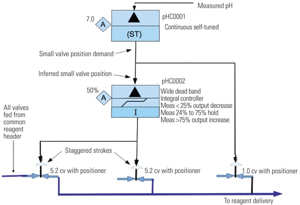
A second controller (pHC0002 in Figure 6) is added and configured with integral action only and with a wide measurement error dead band. This controller functions to drive the larger valves while allowing the smaller pH trim valves to remain in control range. If the position demand to the small flow valve is less than 25%, then controller pHC0002 output integrates to close the larger flow valves. If the position demand to the smaller valve is 25% to 75%, then pHC0002 holds its output. If the position demand to the smaller valve is greater than 75%, then pHC0002 integrates to open the larger flow valves. The larger flow valves are staggered and overlapped stroke calibrated. This configuration is used to gain as much range-ability as practical with the smaller flow valves providing very fine reagent flow adjustment.

6. Second controller. New controller functions and valve set-up. Source: NRG Energy Controller pHC0001 is a continuous self-tuner type that continuously adjusts the gain and integral settings to obtain desired process response. The response characteristic objectives are determined and programmed by the control engineer. Normally, the overshoot goal is 0.25% with 30% dampening. A pre-tune bump test provided initial “centered” settings. The continuous self-tune proportional band (pband) adjustment range is 100 to 10,000, and the continuous integral time adjustment range is 0.50 to 50.0. These settings enable the controller to self-adjust the tuning parameters over the entire influent flow range and pH value range that can be encountered. The pond volume and length serve as an averaging buffer, allowing the self-tuner to adjust for changing conditions. That is, as the pH value of the inlet changes with the resultant process gain change, the self-tuner will readjust the tuning settings.
Because the control takes place at the pond inlet, oscillations that occur as the controller “readjusts” are not a problem for the pond outfall. Swings are minimized relatively quickly with the self-tuner controller. Self-tuning takes minutes, as compared to hours of continuous swings with the original pneumatic controller (end-to-end oscillation will last as long as the influent pH is below a value of 5 and flow is present). In addition, self-tuning initializes the controller each time adjustments are made, so there is no undesirable oscillation due to changing gain (pband), when there is a process measurement to setpoint error.
Following recommended practices for controlling pH (from our control engineer counterparts in the process chemical world), the system described here has proven itself in operation on a sediment pond at two NRG Energy plants and is a guide for planned future retrofit projects. Furthermore, adding a digital self-tuning controller has resolved the problem of controlling sediment pond pH in a one-stage system.
— Donald A. Andrasik (don.andrasik@nrgenergy.com) is a senior DCS engineer for NRG Energy assigned to Morgantown Generating Station and is a member of ISA POWID Executive Committee. This article is based on a conference paper presented at the 2012 ISA POWID Conference.