Hydropower is the oldest renewable energy source, but aging dams require periodic maintenance. A stabilization project that added high-capacity post-tensioned anchors and new concrete enhanced the Bagnell Dam, positioning it as a safe and reliable source of power for the future.
Hydropower has been providing flexible, low-cost, and low-emission renewable energy for more than 100 years, but the benefits go well beyond just the generation of electricity. Many hydropower facilities provide flood control, irrigation, water supply, recreational opportunities, and more.
Yet, hydropower faces a number of challenges. In April, POWER Senior Associate Editor Sonal Patel reported from Waterpower Week in Washington, D.C., an event hosted by the National Hydropower Association (NHA). Patel wrote that Linda Ciocci, president and CEO of the NHA, had suggested during the event that the hydropower industry was “struggling to stay relevant amid the rapidly unfolding energy transition, which has seemingly favored wind and solar over other forms of generation.” Ciocci said the industry needed to “step up our game” to address the devaluation of hydro resources and the financial squeeze that stakeholders are experiencing as more expectations are placed on plants.
The fact that hydropower has been around so long means many facilities are growing old. Upgrades often focus on technology. A recent report published by the International Hydropower Association includes a section on modernization. It says, “A growing proportion of the global fleet of hydropower assets is transitioning to digitalised systems and processes.” While the report suggests technology is changing the way hydropower projects are designed, operated, and maintained, it doesn’t address the structural limitations that older units sometimes face.

Bagnell Dam: A Depression-Era Marvel
The Bagnell Dam on the Osage River in Missouri offers a case in point. According to Lake of the Ozarks history buff, Mike Gillespie, who manages a website with facts and figures about the area, the Bagnell Dam was designed by Stone & Webster Engineering Co. in the late 1920s. Construction began on Aug. 6, 1929, and was completed in April 1931, at a total cost of $30 million. The facility was originally owned by the Union Electric Light & Power Co., now Ameren Missouri.
The Lake of the Ozarks, which covers more than 54,000 acres, was created by the dam. The site of the dam was chosen for a variety of reasons, according to Gillespie. Among the major considerations was the presence of a projecting point on the south side of the floodplain directly opposite a steeply sloping ridge on the north side, he says. The combination restricted the floodplain valley to one-half mile in width, which was narrower than the average width of the floodplain. Furthermore, bedrock at this point was relatively close to the surface—about 20 feet below the mean level of the floodplain.
Bagnell Dam is a concrete gravity dam, which means the weight of the structure is used to counter the lateral force of the water in the reservoir. Gillespie says a typical cross-section is shaped like a right triangle. The base is anchored to underlying bedrock with the vertical wall facing the lake and a slope on the downstream side.
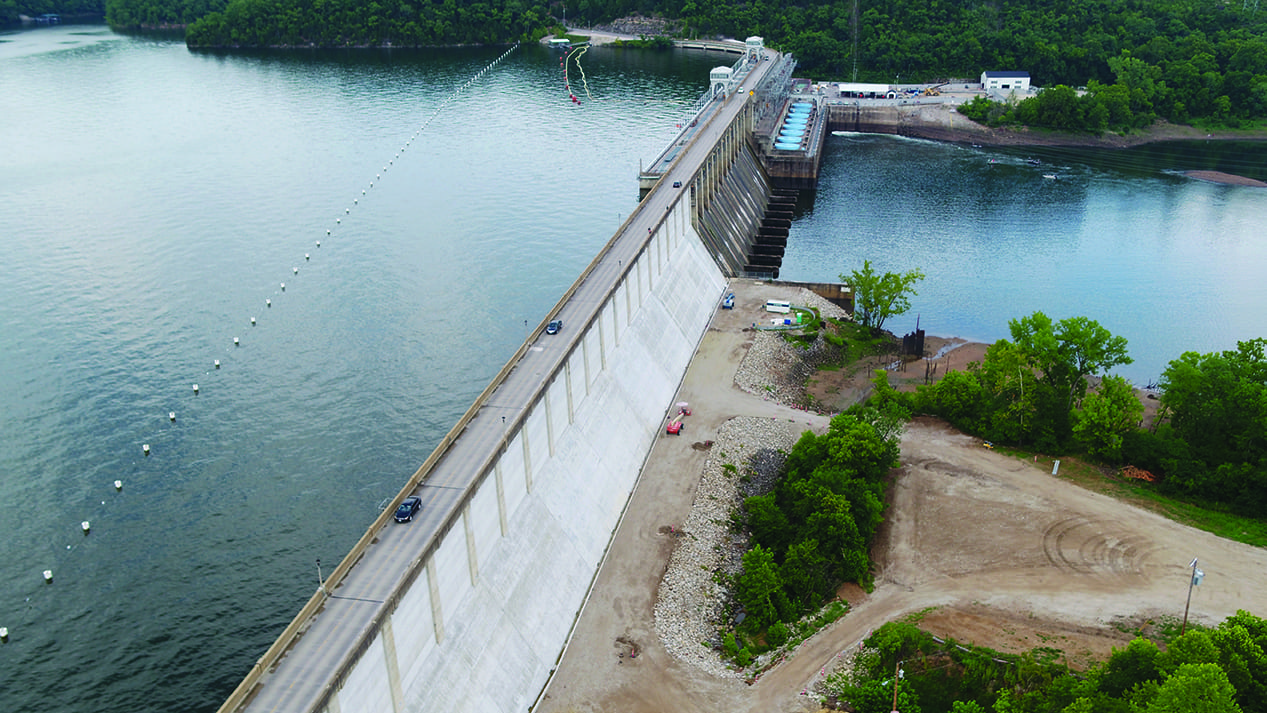
The dam is 2,543 feet long and consists of three sections. The abutment section (1,512 feet) is a solid wall rising from bedrock to the roadway level. It forms the north and south ends of the dam and is 93 feet wide at the base. The spillway section (520 feet) forms the middle portion of the dam. It includes five sealed sluiceways at the base and 12 flood gates at the top. The base of the spillway section is wider than the rest of dam—131 feet. The headworks or powerhouse section (511 feet) sits over the original bed of the Osage River. It consists of eight turbines plus one smaller station service unit, according to Gillespie.
Enhancing Dam Safety
In 2017, Ameren Missouri embarked on a plan to enhance safety at the Bagnell Dam. The utility contracted with MC Industrial, a McCarthy Holdings company, to complete an 18-month-long, $53 million stabilization project, which included the installation of a series of new anchors and concrete on the downstream side of the dam to improve overall safety, efficiency, and reliability. It was the first major structural update to the dam in more than 30 years.
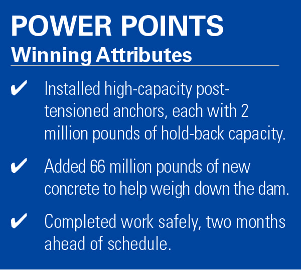
Work included three parts: installation of 67 new post-tensioned anchors to help hold the dam to the underlying bedrock; addition of more than 66 million pounds of new concrete to add mass to the dam; and a new concrete overlay to replace worn and cracked concrete on the east and west sections. This type of work is viewed as a best practice and has been implemented on dams around the world. Still, the job scope demanded expertise in heavy civil works and major dam rehabilitation to ensure a safe and high-quality outcome.
The project team mobilized in March 2017 and work began the following month. Among the significant achievements were placement of 17,000 cubic yards of concrete; addition of 67 post-tensioned anchors, each with a 2-million-pound hold-back capacity; installation of 198 foundation drains; removal of 3 inches of concrete off the face of the dam using 30,000 psi water sprayed over a 100,000-square-foot area, using two hydro demolition machines (robots) built specifically for the project; installation of 33 anchors over the spillway, which required a large temporary steel work platform to perform the work; and overlaying 9 to 12 inches of sloped concrete (Figure 1) on the downstream side of the dam (a 55,000-square-foot area). In all, the total hold-back capacity of the dam was increased by 200 million pounds.
 |
|
1. The Bagnell Dam stabilization project increased the hold-back capacity of the dam by 200 million pounds. In addition to the installation of new anchors, overlaying concrete on the downstream side of the dam helped to achieve this improvement. Courtesy: MC Industrial |
As the general contractor on the project, MC Industrial was responsible for contract management, overall project controls, primary planning and scheduling of the project, safety management, and engaging with the owner and engineer to ensure their interests and concerns where properly addressed. The company also self-performed all of the civil and concrete portions of the project, including the excavation and backfill, underground piping, formwork, rebar installation, concrete placement, demolition of shear keys, site establishment, and replacement.
A Team Effort
“We partnered with Brayman Construction, who installed the high-capacity post-tensioned anchors, and Rampart Hydro Services, who performed the hydro demolition on the existing downstream dam face,” Mike Hartwig, project manager with MC Industrial, told POWER. At its peak, the workforce totaled 80 crew members.
“Some of the work performed on the project was extremely technical and required a lot of specialized training, such as the hydro demolition and anchor drilling,” Hartwig said. “For these positions, as well as key field leadership positions, trained employees were brought to the project by MC Industrial and our partners Brayman and Rampart. We also worked with our local union partners to ensure the project had the right employees to meet the needs of the project.”
Working under an active spillway presented some challenges. Space was tight downstream of the lake and above the Osage River. Yet, the project team maintained a safe environment not only for workers, but also for pedestrians and traffic on the roadway. MC Industrial finished the project with zero recordable injuries during the 106,741 self-performed man-hours logged, Hartwig said.
The team planned the work from west to east, and the crews performed tasks by following each other down the dam in a typewriter effect. Hydro demolition was first, followed by shear demolition. Anchoring crews came next, then concrete infill, and finally overlay crews. As with most complex projects, problems arose that interrupted the work flow, but the team’s collaborative approach overcame the challenges with innovative solutions.
For example, one unforeseen problem the team encountered arose while concrete was being placed on the downstream face of the dam. Hartwig explained that this portion of the dam is inclined at a 56-degree angle and formwork was required to overlay the concrete. The inward sloping geometry resulted in small air voids, called bug holes, becoming trapped on the surface of the concrete when the forms where removed. The MC Industrial team searched for a solution, attempting many different placement and consolidation techniques with little success. Finally, the team found a permeable form liner, called Duoguard Formtex, manufactured in the Netherlands. This lay-flat permeable liner allowed water and air to escape during concrete placement, resulting in a clean, uniform finish. The liner also added strength to the concrete and is expected to reduce time-related wear and tear.
Another time-saving tool used on the job was MC Industrial’s in-house developed project tracker. The tracker utilizes a shared database to monitor work progress. It tied into the project’s 3D model and allowed use of real-time information in decision-making. The software was helpful in planning and coordinating tasks appropriately. It also provided a snapshot of progress with colored visuals from the model. The tool helped the team complete the project two months ahead of schedule.
A Stable Future
Another important structural enhancement was the installation of high-capacity post-tensioned anchors. Hartwig said the anchors were needed to supplement and eventually replace anchors that were installed in the dam in the 1980s. The earlier anchors were engineered to have an approximate lifespan of 30 years, but there was really no way to test the existing anchor integrity.
The new corrosion-resistant anchors are a different style. Each anchor includes up to 55 sheathed strands, with varied lengths depending on the dam-to-bedrock interface—the average length was 120 feet. The improved design also includes a re-stressable head, which will allow anchor inspections to ensure long-term functionality.
To begin the anchor installation process, a hole was drilled through the dam into bedrock to a designed depth. The amount of water infiltrating the anchor hole was monitored and recorded. The hole was then filled with grout and re-drilled on a subsequent day, once the grout had sufficiently hardened. Then the water infiltration was recorded again. The process was repeated until the water infiltration rates had reduced to a specified amount. A corrugated high-density polyethylene (HDPE) anchor sheath and the anchor were then installed into the drilled hole, and grouted into place. Once the grout cured, the anchor was stressed with a hydraulic jack and locked at the applicable loading. Each anchor added 2 million pounds of hold capacity to the dam.
“With the Bagnell Dam dating back to the Great Depression, and without a major structural enhancement in more than 30 years, new technology and outside-the-box construction methods had to be engineered to continue the strength and durability of the historic landmark,” Hartwig said. The successful project is a great example of how the industry is keeping hydropower relevant by “upping its game.” ■
—Aaron Larson is POWER’s executive editor.