When most of today’s wind projects were developed, first costs were the focus; operations and maintenance (O&M) costs were largely unknown. Now, with hundreds of turbine models in operation—sometimes at a single site—O&M complexity is magnified, which makes understanding common failure modes and how to prepare for handling them essential.
Over the past few years, wind generation projects have become prominent features of the North American landscape and of the utility infrastructure. In spite of their variable production load onto the grid, wind has proven to be a solid contributor to inexpensive energy delivery.
Including current production and the many new projects under way, U.S. wind energy peak capacity should pass 75,000 MW nameplate capacity by the end of 2015, according to the American Wind Energy Association’s (AWEA’s) “Second Quarter 2014 Market Report.” Wind is providing a steadily increasing share of the electricity generated in the U.S.: 4.1% in 2013 compared to 3.5% in 2012 and 2.9% in 2011. That’s the equivalent of 14 average nuclear reactors or 53 average coal-fired generation facilities. That’s a lot of energy, regardless of the source.
Developing a New Generation Sector
The first wind generation plants were installed in California in the 1980s, but it took until 1999 for the industry to hit the 2,000-MW threshold. Around that time, the first state Renewable Portfolio Standards (RPSs) were passed, ushering in explosive growth. The combination of the federal production tax credit (PTC) and state RPS policies have grown the industry 25-fold since 1999. During 2012, the U.S. wind industry installed more than 13,000 MW, and a similar amount is under construction for the 2014–15 timeframe, designed to take advantage of the 2013 extension of the PTC.
It is, of course, unknown what will happen in the future regarding federal and state government encouragement for growth, but there are still many growth markets that can benefit from this low-cost energy source, especially on a distributed basis near large power consumers in the Northeast and the Gulf Coast. Utilities are continuing to invest in wind power, because they are interested in a hedge against volatile fuel prices and future carbon regulations. There are also unopened markets, including the southeastern U.S., that may well continue to become more competitive as turbines are scaled up and prices fall.
To put some perspective on the effect of the PTC and other investment incentives that have been available for wind and other new energy initiatives, it is important to consider the nature of the electricity market today compared to how it was when today’s nuclear and coal sources were developing in the 1960s and 70s.
Many regions of the U.S. are now more or less deregulated at either the generation or consumer level or both, but during the big energy construction boom starting 50 years ago, most utilities were public/private ventures with investor ownership but with revenues tightly controlled by various public utility commissions. For the construction of long transmission lines, large coal-fired sites, and the entire nuclear power generation fleet, funds were raised primarily by private investments, but with returns based on substantial rate increases to energy consumers.
When the wind energy market was developing, the scenario was changing, and the U.S. Congress chose the production tax credit scheme in 1992 as the best way to encourage the development of this new technology while avoiding cost increases for consumers. The wind power industry has been on a roller coaster of PTC expirations and reapprovals since then, which has been a burden to investment in new manufacturing facilities, where boom and bust cycles are devastating.
When the PTC has been allowed to expire, the U.S. wind industry has seen between a 75% and 93% drop in annual installations. Nevertheless, according to the U.S. Department of Energy (DOE), domestic content has increased dramatically in wind turbines and their related components installed in recent years.
All this being said, the cost of wind energy has fallen dramatically, and wind power is cost-competitive in many regions of the country. The U.S. has a wide portfolio of energy sources, and a wise path would be to provide a balanced mix to provide low-cost, dependable, and regionally produced electrical energy for the foreseeable future.
This expansion of power generation capabilities has also provided a great avenue for corporate growth and workforce development. As an example, Shermco Industries has been testing, repairing, and remanufacturing electrical systems and equipment for utilities and industrials since 1974, long before the development of viable wind energy. Today the company has expanded dramatically, in part to take advantage of emerging energy markets, and now has 16 locations and more than 1,100 employees in the U.S. and Canada. Without ongoing investment in the energy infrastructure, we wouldn’t have had that opportunity. And we are not alone. According to AWEA statistics, there are now more than 50,500 jobs directly related to wind energy manufacturing, construction, operation, and maintenance.
All of this introduction might seem a bit distant from maintenance planning, but understanding some of the decisions that have been made regarding wind projects will help explain why operations and maintenance (O&M) is such a critical and often underfunded segment of the industry. In order to structure a wind project to provide a reasonable return to investors, the financial model of the project had to be carefully researched and constructed, and providing the lowest cost equipment that met the specifications seemed like the right thing to do.
Financial Realities Drove Design
To drive those financial efficiencies, turbine manufacturers developed equipment to be low cost, lightweight, yet with high power output ratios. Unlike the development of traditional electrical machines, which were designed very conservatively, wind turbines are often a bit closer to the edge of the design criteria. So rather than designing large, heavy-duty machines and scaling them down in size and up in power, they put their best efforts into hitting that sweet spot of power-to-weight ratio from the very beginning.
This has been effective for the most part, but, as we will see, there are some issues left to the O&M teams to solve. Other turbine components have also been affected, especially the gear boxes used in most traditional designs.
This financial strategy has also affected the reliability of the balance-of-plant maintenance at many farms as well, where the short lifecycles of transformers and often unreliable underground collection systems have increased down time and service calls. But that’s another article. Compared to traditional power generation facilities, the risk is spread over many generators, so the total effect of these design weaknesses is less than if a single 300-MW steam turbine failed. Nonetheless, it is difficult to maintain a facility where the financial expectations allowed for little budget to be allocated for major component replacement.
So what should you expect if you find yourself responsible for a wind farm, and especially regarding the generator (Figure 1)? This article reviews what “expected wind turbine life” really means, what failures can be expected and when, how failures are often managed currently, and some options for planning successful future projects.
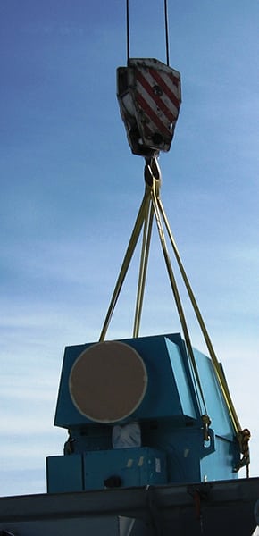 |
| 1. A wind generator being removed and replaced. Courtesy: Shermco Industries |
Let’s start with an overview of the turbine components and how generator reliability fits into overall turbine performance.
Turbine Life vs. Component Life
What does “life expectancy” really mean for these complicated machines? Most wind projects base their financial projections on a 20-year model, and wind turbines are designed to meet or exceed that expectation based on the wind loads as defined by IEC6140-1. That doesn’t mean that every component will perform reliably for 20 years without maintenance, repair, or replacement any more that the 30-year design life of a steam turbine facility means that nothing will need replacing.
However, with proper condition-based maintenance and a great operating team, reliable and profitable production can be achieved for the life of the equipment, which will be quite possibly much longer than 20 years. Remember, an end-of-life event at or beyond the designed expectancy is not a failure.
In a traditional wind turbine drive train, the blades drive a slow-speed, high-torque main shaft directly connected to a speed-increasing gearbox with the high-speed output shaft coupled to an AC generator. The electrical output of the generator is then attached to the collector system either directly or through an electronic convertor. There are a lot of ancillary devices required to control blade pitch, turbine yaw, brakes, and other components. Those components also can have life expectancy issues, but they are generally considered normal maintenance wear components.
So, in achieving the expected 20-year life, most effort is focused on the major components. Certainly, the tower and foundation are critical as well, but good engineering practices have avoided all but a few structural failures. Blades have had some history of early failures as well, but the quality seems to have improved dramatically, and there don’t appear to be any systemic reliability issues on newer turbines, in spite of the very few recent failures.
Main shafts are typically very large forgings and have few issues beyond damage due to main bearing failures—a rarity in early failures, but it becomes more common after a few years of service. Like most bearing failures, it can be a relatively inexpensive repair if identified early. Nevertheless, repairs normally require large cranes and unplanned down time.
Gearboxes are the most costly and problematic components, and some of the failures do appear to be related to design and manufacturing problems and exist throughout the fleet. Again, early failure identification can reduce operating costs, but some gearboxes are just not going to hold up for 20 years regardless of the level of maintenance. Many upgrades are available, and new engineering solutions for the common failure modes are developed with each revision. A lot of maintenance time and budget are allocated to gearbox reliability and, again, the gearboxes utilized in the newer designed turbines appear to be much more reliable.
Lastly, we can look at the generator and the electronics that support its operation. Several types of generators are utilized, mostly operating at 575 or 690 VAC. A few designs operate at higher voltages, but those are exceptions. The most common generator type is a doubly fed induction generator with an electronic drive feeding a wound rotor through a slip ring collector assembly. In these designs, the rotor windings can themselves generate power above certain rpms, and the total rated output of the generator is calculated based on both stator and rotor outputs. The power is then combined by the control system and sent to the step-up transformer for transmission to the substation. These generator designs are normally a fixed frequency output generating at a grid-synchronized 60 Hz.
In some newer designs, permanent magnetic rotors are used to avoid the need for external excitation. Many turbines also utilize squirrel cage induction generators. In both of these designs, the output is converted regardless of frequency through an AC/DC-DC/AC insulated-gate bipolar transistor (IGBT) convertor assembly and then synchronized with the grid. In both of these designs there are no slip ring/carbon brush assemblies to maintain, but the larger electronic packages can be problematic. There are also a few direct drive models available where a multi-pole generator is driven at low speed (17 to 18 rpm) and the energy produced is fully converted. All of these newer designs are intended to improve reliability and serviceability.
Generally speaking, with a wide range of manufacturers, owners, third-party O&M groups, and specialty service organizations, the reliability experiences are diverse and fractured. Unlike traditional fossil generation facilities, where there are just a few generator models in operation, some wind sites have 400 or more distinct turbines—often from multiple manufacturers. There is an advantage in having the risk spread over multiple machines, as turbine maintenance outages often affect only a small percentage of the project’s output. On the other hand, it is certainly more complicated to manage even normal maintenance activities on that many turbines, especially considering that they are 300 feet in the air.
Even if all of the major components of a turbine need to be replaced (and that would be highly unusual), it is often only a two-day job—unlike the weeks required for a complete overhaul of a traditional generator. Of course, there are decades of service records, procedures, and maintenance strategies in place for steam and gas turbine generators. Wind O&M teams are often still developing the experiences to define and maintain strategies, a task complicated by the multitude of manufacturers and models compared to traditional generators. Also, keep in mind that testing and servicing these machines is often performed without much supervision—after climbing a 300-foot ladder. Well-experienced and dependable personnel are critical in all aspects of wind project maintenance.
Wind turbine original equipment manufacturers (OEMs) have made great strides in developing newer, larger designs that are more robust, and they seem to be addressing both maintenance and safety-related issues in their newer designs. The statistics show that there are still too many failures, especially related to maintenance, but as failure modes are better understood, more-dependable machines are being built. According to studies surveying traditional industrial and utility applications, motors and generators over 100 kW experience service lives from 25 to 38 years, so at least 20 years for a wind turbine generator does seem a reasonable goal.
Wind Generator Failure Modes
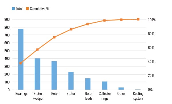
Understanding the common failure modes and what might be done to extend the life of a generator is critical to providing the reliability needed by project owners. Most of the generator designs utilized in wind turbines are conceived and often manufactured in Europe, utilizing insulation systems that reflect historical materials and processes. Several common failure modes have been identified, many of which can be traced to identifiable root causes. However, specific failures remain difficult to identify, as minor failures can lead to catastrophic electrical failures not directly related to the root cause. In addition, it has been rare to receive alignment, vibration, or power quality data points on individual failed machines. Below are examples of the common failure modes for these generator types.
Rotor Insulation. Wound rotor insulation damage mostly appears in two forms. The most common is a failure of the supporting materials—banding (Figure 2), ties, wedges, and the like—to function adequately based on overspeed conditions or loading electrical forces.
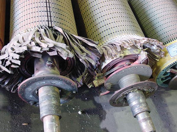 |
| 2. Rotor banding failure due to overspeed conditions. Courtesy: Shermco Industries |
Some earlier machines were initially designed to operate synchronized to 50 Hz rather than the 60 Hz utilized in North America, and it has been thought that the resulting increase in rotational speed was not fully taken into account.
Electrical failures, the other common mode, might be related to the same mechanical weaknesses and the resulting vibration and abrasion, but because wound rotors are all energized by IGBT control circuits, there should be some consideration that damage was also due to the typical elevated electrical stresses often generated by these drives, especially if the excitation circuit has filters that have failed and are unannunciated through the SCADA system.
Some of the rotor windings also operate at higher voltages than the stators—up to 3,000 VAC—and it is critical that the insulation system account for some level of voltage endurance stresses as well as short-term dielectric properties. There is not yet enough data compiled on the permanent magnet style generators regarding rotor failures, as most are still operating under warranty from the generator OEMs, but some of the older designs (<1 MW) have shown that pieces of the magnets can come loose, resulting in catastrophic failures of the stator windings.
Rotor Leads. There have been many issues with the rotor leads in doubly fed induction generator (DFIG) designs. These pass the excitation current from the collector rings to the windings, and any power generated by the rotor back out the same way. They can be subject to high heat if a bearing fails, as well as vibration, and, of course, to poor electrical connection or supporting structures at either end. The good news is that most of these failures can be repaired up tower, utilizing improved conductor insulation and supporting materials. Nonetheless, this is a very common failure mode, and entire fleets have been retrofitted to avoid unplanned events.
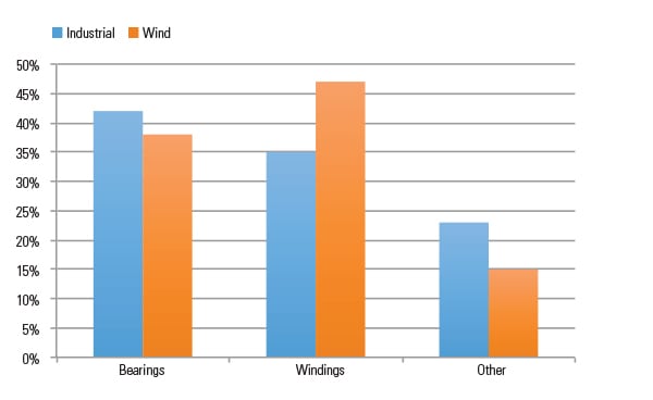
Bearings. Bearing failures are a large cause of generator down time and are arguably the easiest failures to prevent. Proper lubrication, alignment, condition monitoring (thermal and vibration), and the effective management of induced shaft currents are the key to bearing longevity.
However, maintaining a fleet of wind turbines with dozens of critical bearings in each can be a daunting task. Auto-lubrication systems have helped with under-lubrication issues, but the lubrication systems themselves must be maintained and properly adjusted, and the cyclical nature of wind generation does not lend itself well to strictly time-based lubrication. Exit ports for the expended lubricant must be kept free, and the grease itself must not separate in the auto-lube reservoir.
Most generators do have thermal monitoring on the bearings, but a lot of damage can be done before enough heat is created to trip the sensors. Many newer turbines include vibration monitoring as well, but there are tens of thousands of turbines that have not been retrofitted.
Induced current on the shaft has continued to create problems with shortened bearing life. Grounding brushes have to be maintained carefully and are easy to forget for the technician. Insulated bearings or bearing housings have also helped, but those systems must be tested regularly as well for continued effectiveness. Many end users now specify ceramic hybrid bearings, in spite of the much higher cost. These have proven to be a good solution and require no special maintenance procedures.
Stator Windings. Stator winding insulation failures can also be divided into several categories, but most fall within normal industrial failure modes, with the exception of the loss of magnetic wedges. That mode will be considered separately. Because most of the stators operate at low voltages, partial discharge is not seen to play much of a role in these failures, but especially where the initial excitation voltages are supplied from an IGBT drive by induction from the stator windings, there is always the possibility of damage from the peak voltage. Most of these windings do utilize mica as part of the strand and ground wall insulation systems, but most also utilize polyester (PET) film, which is generally unpopular among North American generator designers.
Collector Rings. Collector rings (generator slip rings), the metallic/carbon brushes and the brush riggings and holders together make up the collector assembly for DFIG design generators. Like similar industrial applications, these wear over time and are considered replaceable components. However, in an effort to minimize maintenance, they are often fitted with long brushes that, over the period of their life, generate a lot of conductive dust. It is critical that these areas be checked regularly and that a good cleaning regime be followed to avoid flashovers. These are not normally fatal to the equipment, but they will immediately bring a turbine off line, and it is never good to have arc flashes up tower.
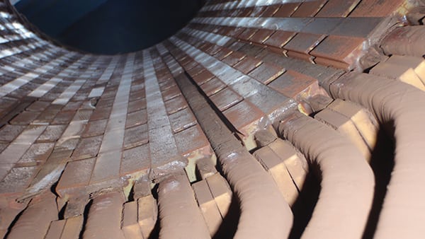
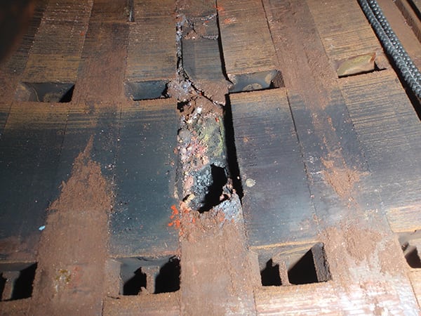
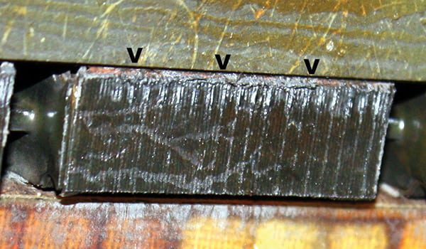
Magnetic Wedges. Most of the newer and larger turbines installed during and since 2008 utilize larger, more robust generators (2 MW and larger) with preformed, mica-insulated stator coils and well-designed mechanical components. Additionally, most of the older 1.5-plus-MW designs have been upgraded with many of the weaknesses of the earlier designs corrected. However, in many of the newer larger designs, stator coil wedging utilizes high–ferrous content composites to smooth the flux fields and increase the efficiency of the generator.
All of this is good in theory, but, due to various reasons—including materials, manufacturing processes, and application rigors—these wedges have a tendency to loosen, which leads to several bad results. They can create a conductive dust circulating through the windings that will lead to eventual electrical failure. They can break into larger pieces and pierce the ground wall, creating an immediate and spectacular ground fault. And, of course, coils can become loose without the proper support. Additionally, the slot laminations can be damaged by wedge movement abrasion, preventing future remanufacturing without major expense.
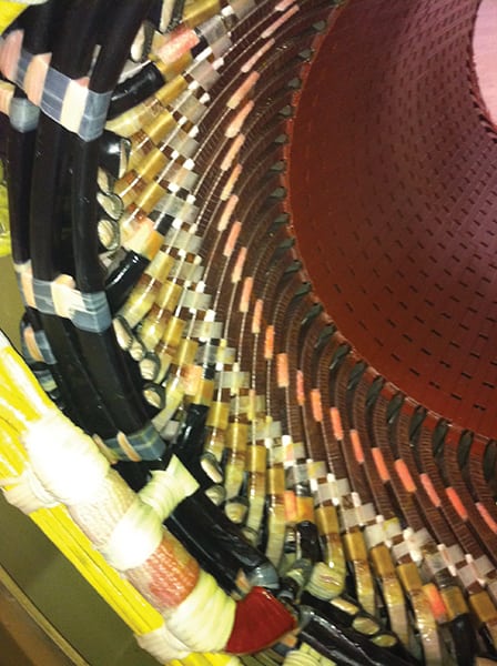
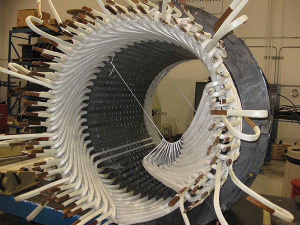
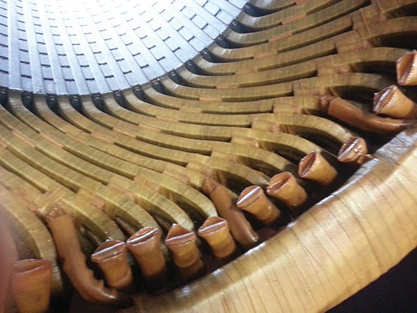
None of these failure modes (Figures 3 to 5) is easy to mitigate, and all require removing the generator from the turbine. To date, there is no effective way to test for this failure mode beyond visual inspection and, other than scheduling for replacement, there is not a lot that can be accomplished anyway for a reliable solution.
https://www.powermag.com/wind-turbine-generator-maintenance-what-to-expect-and-why/
