Sometimes overlooked and underappreciated, a power plant condenser can make or break your efficiency and power delivery goals. Understanding how important a role your condenser plays is a good step toward greater heat rate awareness.
As part of a university class on power generation systems that I teach, I show my students a Sankey diagram of the energy flow of the U.S. electrical generation system (Figure 1). Sankey diagrams are wonderful creations, which allow an easy visualization of a complex set of inputs and outputs to a system, as well as the relative impacts of these flows. When one views the Sankey diagram created by the U.S. Energy Information Administration (EIA) one is immediately struck by the large output of the graphic labeled “conversion losses.”
Last year, one of my students raised her hand and asked me, “So, that giant section of the diagram is all wasted energy?”
“Yes,” I replied, “although some of it is necessary due to thermodynamic limits. For a typical Rankine-cycle power plant, the condenser dumps more than 50% of the input heat to the environment.”
“But that’s horrible! ” she replied, with a rare passion from students (especially when taking a late-night class, when many students are somnolent). “Can’t we do something about it?”
I paused, and then nodded to her, “Perhaps you’ve just found your calling.”
An e-mail from her a year later revealed that, rather than entering my world of power plant efficiency, she had instead taken work designing roller coasters for a theme park chain. Well, you can’t win ’em all.
And, unfortunately, many steam power engineers also feel as if they can’t win the battle to make their plants more efficient. The multiple pressures of emissions regulations, budget cuts, and competition with gas turbines and renewables can leave Rankine-cycle power engineers feeling that efficiency improvements are not even on the proverbial back burner; instead, they’ve been put into a plastic bag and stuck in the deep freeze.
That attitude leads to missed opportunities, which is why this article focuses upon one of the components that accounts for part of the significant energy losses in our power generation system—the condenser. You’ll learn ways in which both condenser performance and operation could be improved to help position a Rankine-cycle power plant to compete more effectively within the turbulent power generation environment most of us face.
Condenser Fundamentals
In a typical steam power plant, steam is sent to various stages of the turbine in order to produce power. After the steam exits the final stages of the turbine, where it has no more energy to be economically converted into power, it must be condensed back into a liquid in order to allow it to be pumped to the feedwater heaters, and subsequently the boiler. In basic operation, the condenser is a relatively straightforward device:
■ Low-energy steam or saturated steam enters a chamber filled with rows of heat exchanger tube banks.
■ Cooling water is passed through the inside of the heat exchanger banks, and heat is transferred from the steam to the cooling water.
■ The steam condenses and is collected in the hotwell in the bottom of the condenser.
■ The cooling water is either dumped to the environment (in an “open-loop” system) or circulated to cooling towers for re-use (in a “closed loop” system).
Some power plants utilize a different method of heat transfer, where the low-energy steam is passed inside heat exchanger tubes exposed to the air, and forced-draft fans blow air over the tubes to extract heat and condense the steam. These air-cooled condensers are less efficient overall, but are necessary when the power plant is located in a region where suitable water is at a premium. As utility-scale air-cooled condensers are rare, this article instead focuses on water-cooled condensers.
Condenser Performance
For a given steam turbine system, the performance of the condenser is largely a factor of how efficiently heat can be transferred from the steam to the cooling water. The faster that heat can be transferred, the faster the turbine exhaust steam can be condensed into liquid water.
One metric of this condensation efficiency is the condenser pressure, often measured as vacuum. A condenser that can pull a stronger vacuum not only results in a higher cycle efficiency but also more potential power output. For example, a power plant with a feedwater flow rate of 2.5 million pounds per hour and condenser pressure of 3 inches Hg would see a heat rate improvement of nearly 6% if station engineers could reduce the condenser pressure to 1 inch Hg. This improvement alone could satisfy most of the Environmental Protection Agency’s (EPA’s) much-debated heat rate improvement goals for existing coal-fired power plants.
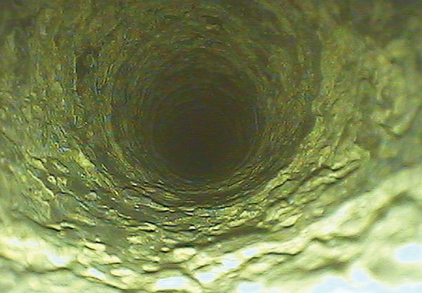
Tube Fouling. Condenser heat transfer is greatly hampered by fouling of the heat transfer tubes. In addition, long-term fouling deposits can increase tube corrosion by allowing corrosive chemical reactions to “hide” under the deposits.
While in rare cases scale deposits can form on the steam side of the condenser tubes, most tube fouling occurs on the water side of the tubes. Fouling can further be subdivided into inorganic and organic causes. Inorganic fouling is often composed of calcium carbonate and calcium phosphate, but it can also include manganese deposits, clay, and fine rock silt. In some cases, pieces of rotting or degrading cooling towers can become trapped within the condenser tubes or upon the surface of the tubesheet.
In the case of power plants that use seawater or river water in their circulating water system, fouling can take the form of mud, organic slime, and marine plants and animals. For example, the Madras Atomic Power station in India has found no fewer than 48 different types of marine organisms living within its cooling water systems, ranging from barnacles and snails to tube worms and sea anemones. One wonders if the owners have considered installing glass windows in their condenser cooling water tunnels, and charging admission as an aquarium.
Freshwater cooling systems tend to experience much less biofouling, and for closed-loop systems biofouling is often controlled by regular chlorination. Most slime-producing bacteria are killed at chlorine levels greater than 0.5 ppm to 1.0 ppm for an hour, although high levels of chlorine can also damage wooden components and structures in cooling towers.
The effects of condenser fouling can be serious. In one instance a nuclear power plant lost 50% of its generating capability due to a biological film within its condenser tubes.
Many power engineers believe that prevention is the best medicine for condenser fouling, and chemical treatment, such as reducing the pH of the circulating water by adding small quantities of sulfuric acid, is a common practice. Once the fouling has accumulated, however, some sort of physical cleaning will be required. Several cleaning methods are available for condensers, both online and offline (Figure 2). Using plastic or metal brushes to clean the tubes can yield a benefit of approximately 0.1 inches Hg in vacuum, while a more involved mechanical cleaning can reduce condenser pressure by 0.6 inches Hg or more. An average improvement in condenser vacuum of 0.35 inches Hg can result in a 30 to 70 Btu/kWh heat rate improvement, resulting in an annual fuel, operations, and maintenance savings of $60,000 for a 500-MW power plant (Figure 3).
Electrical Efficiency. Condenser systems need either circulating water pumps to supply them with cooling water or fans to supply fresh air to air-cooled tubes. (Because most air-cooled condensers are relatively new devices, they tend to already have fairly modern motors and controls; thus, the potential for savings is less.)
Water pumping systems tend to require from 8 to 12 hp/MW of generating capability. The main circulating water pumps and hotwell pumps combined can use from 0.5% to 1.0% of the total unit power, and old or inefficient pumps and motors can result in a significant heat rate and cost penalty.
A 2009 study by ABB (Power Generation: Energy Efficient Design of Auxiliary Systems in Fossil-Fuel Power Plants) estimates that in a typical 500-MW power plant, retrofitting the circulating water and hotwell motors with variable-frequency drives could result in an annual savings of more than 10,000 tons of CO2, more than $350,000 in avoided fuel and operations costs, and a payback period of under two years. Making a more modest investment in simply replacing the motors with high-efficiency, low-power-factor units would result in an annual savings of more than 3,000 tons of CO2, more than $100,000 in avoided fuel and operations costs, and a payback period of less than four years.
Don’t View Your Condenser in Vacuo
Although it’s tempting to draw a boundary around the condenser when evaluating regions for improvement, it’s critical to remember that the condenser and the circulating water system are effectively one functional unit. Because the temperature and quality of the cooling water has a significant effect upon condenser performance, it’s therefore important to consider improvements to the circulating water system contemporaneously with improvements to the condenser. Reducing cooling water temperatures is a sure-fire way to improve condenser performance: A decrease in cooling water temperature of 10 degrees F can improve the overall heat rate of a power plant by 1%.
Some have also discovered that problems with their condenser can lead to severe and unexpected impacts throughout other systems in their power plant.
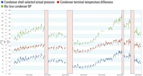
One example is a case where a power plant suffered from severe copper deposits on the inside of its boiler tubes. Investigation of the root cause revealed that the dissolved oxygen level in the feedwater was excessively high, yet an inspection of the feedwater system revealed no obvious leaks. By careful monitoring and diagnostic work, engineers discovered that the condenser suffered from strange decreases in its vacuum levels at high generation loads, but not at low loads (Figure 4). Furthermore, dissolved oxygen levels rose sharply at low loads. This effect was calculated as costing the utility approximately $38,000 per month in lost efficiency and generation. An investigation of the problem revealed a leak in the condenser hotwell, which only occurred under high-vacuum conditions. Repairing this leak not only reduced the dissolved oxygen of the water but also resulted in a heat rate improvement of 800 Btu/kWh.
Capture Condenser Opportunities
Due to its significant effects on the overall performance of the turbine and feedwater systems, your condenser effectively sets the efficiency standard for the rest of your power plant. Recent years have seen many power plants focus on combustion controls, furnace tuning, fuel switches, and turbine upgrades to supply heat rate improvements. Although less attention has been paid to condensers, performing frequent cleaning and maintenance, as well as funding capital improvements to the condenser and circulating water systems, also have the potential to deliver significant improvements to your plant heat rate. ■
—Una Nowling, PE (nowlinguc@bv.com) is an adjunct professor of mechanical engineering at University of Missouri-Kansas City and the technology lead for fuels at Black & Veatch.
https://www.powermag.com/best-practices-for-maximizing-condenser-efficiency/


