- Determining if flow-accelerated corrosion (FAC) might be occurring in the lower pressure circuits.
- Regular evaluations can provide information on the internal deposit deposition rate, which is information necessary to help prevent under-deposit corrosion damage mechanisms.
- Provides information necessary to develop an optimized cycle chemistry for HRSGs.
- Can help determine if the HRSG needs to be chemically cleaned.
The leading heat recovery steam generator (HRSG) tube failure mechanisms are FAC, thermal and corrosion fatigue, and under-deposit corrosion (UDC) and pitting. The corrosion products released by the FAC mechanism are transported from the affected area (typically the feedwater or lower pressure systems) and can eventually reach the HP evaporator tubing, so understanding the deposition in the HP evaporator is an important step in determining if FAC might be occurring. Deposition on the inside of HP evaporator tubing is also a precursor to any of the under-deposit corrosion HRSG tube failure mechanisms. Controlling UDC damage requires, among other steps, removing HP evaporator tube samples on a regular basis to determine the deposition rate. Developing an optimized cycle chemistry for HRSGs is intimately related to understanding the formation of deposits in HP evaporators. And lastly, an evaluation of the internal deposits in HP evaporator tubes can help determine if the HRSG needs to be chemically cleaned.
Structural Integrity (SI) has been conducting internal deposit evaluations on HP evaporator tubes for over ten years and generally follows the IAPWS guidance on performing these analyses (International Association for the Properties of Water and Steam, IAPWS TGD7-16, Technical Guidance Document: HRSG High Pressure Evaporator Sampling for Internal Deposit Identification and Determining the Need to Chemical Clean, www.iapws.org). A standard evaluation consists of the following steps:
- Measuring the deposit weight density to determine the overall loading (indigenous oxide + deposits/reaction products).
- Optical metallographic examination and documentation of cross-sections through the tube, indigenous magnetite, and deposits.
- Measuring the total thickness of the indigenous magnetite and deposit layers from the metallographic samples.
- Scanning electron microscopy (SEM) and elemental mapping by energy-dispersive x-ray spectroscopy (EDS) of cross-sectioned oxide/deposit layers to determine the distribution of elements and whether any reaction products are present within the deposit.
- X-ray Diffraction (XRD) is used to identify the compounds within the deposits, if necessary.
HP Evaporator tube samples should be removed from locations where the deposit buildup is expected to be heaviest. For horizontal gas path HRSGs with vertical tubes, the lead tube (closest to the gas turbine) towards the top of the circuit near the outlet header is generally a good location. For vertical gas path HRSGs with horizontal tubes, the best sampling location may not be as obvious. The first and last tube in the bundle should cover differences in deposition. For either configuration, tubes on the extremities of the bundles where gases can bypass along the duct, or near the center of the HP evaporator if there is a gap between multiple modules, are locations that can have heavier deposits.
Case Studies
The images in Figure 1 show the internal deposit loading coupons from an HP evaporator tube with a high deposit loading value. The deposits were not ruggedly red and were relatively thick. The deposit loading on the hot side (upper coupon) was 49.4 g/ft2. No significant pitting or corrosion was observed after cleaning.
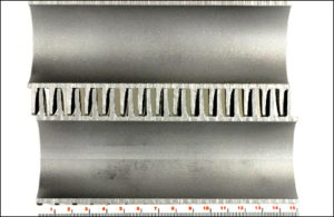
FIGURE 1. Deposit loading coupons before and after cleaning from tube with heavy deposits. 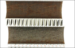
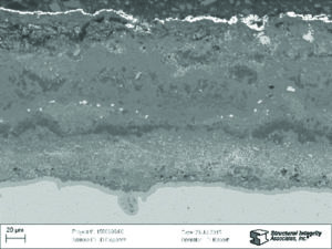
The hot side of the tube was cross-sectioned; optical metallographic and SEM images of the cross-sectioned oxide/deposit layer are shown in Figure 2. The oxide/deposit thickness is 160 microns.
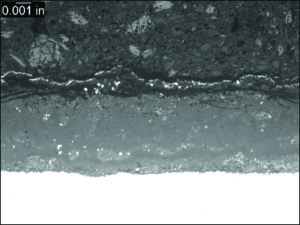
FIGURE 2. Optical metallographic (left) and SEM (right) images through the oxide/deposit layer on the hot side of the tube. The ID surface is facing up in these images. The bright layer along the top of the deposits is from gold coating, which is part of sample preparation.
The EDS elemental maps from the oxide/deposit layer are shown in Figure 3. The thin indigenous oxide layer is clearly visible along the tube metal surface. The deposits contain significant amounts of calcium, phosphorus, and magnesium, moderate amounts of sulfur and copper, and trace amounts of sodium.
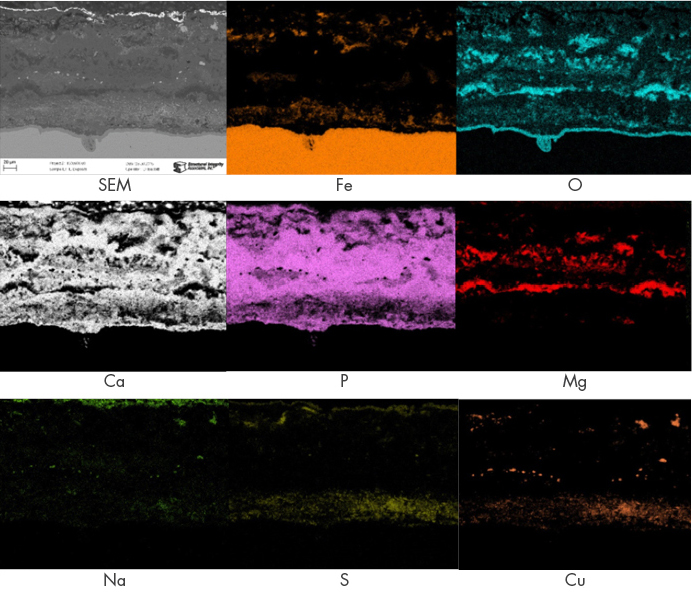
FIGURE 3. EDS elemental maps of deposit layers.
While no evidence of UDC was observed in this tube, the internal deposit evaluation indicated that UDC would be a concern should contaminant ingress occur. This tube is in the region of the IAPWS Deposit Map for HRSG HP Evaporator tubes that indicates chemical cleaning is necessary.
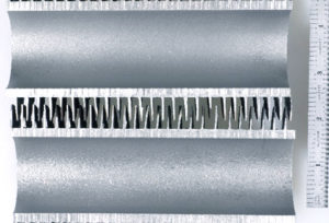
In another example, Figure 4 shows the internal deposit loading coupons from an HP evaporator tube with a low deposit loading value. The deposits were ruggedly red. The deposit loading on the hot side (upper coupon) was 4.7 g/ft2. No significant pitting or corrosion was observed after cleaning.
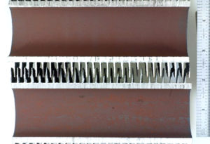
FIGURE 4. Deposit loading coupons before and after cleaning from tube with light deposits.
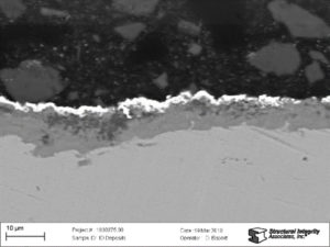
The hot side of the tube was cross-sectioned; optical metallographic and SEM images of the cross-sectioned oxide/deposit layer are shown in Figure 5. The oxide/deposit thickness is approximately 10 microns.
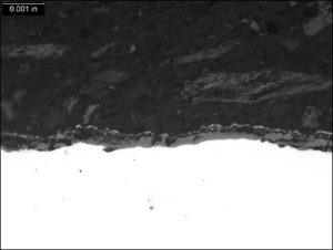
FIGURE 5. Optical metallographic (left) and SEM (right) images through the oxide/deposit layer on the hot side of the tube. The ID surface is facing up in these images. The bright layer along the top of the deposits is from gold coating, which is part of sample preparation.
The EDS elemental maps from the oxide/deposit layer are shown in Figure 6, which show that some level of corrosion product concentration is occurring within the deposits and that the tubes should continue to be monitored. However, these tubes do not currently need chemical cleaning.
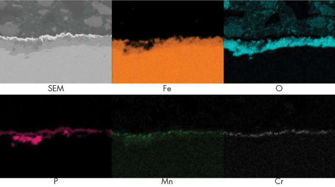
FIGURE 6. EDS elemental maps of deposit layers.