A previous article covered the importance of reverse osmosis (RO) for primary treatment of high-purity makeup water at many power and industrial facilities. The reliability of RO systems is overwhelmingly dependent on proper pretreatment. Suspended solids and other impurities can quickly and irreversibly foul RO membranes, at best resulting in significant costs for membrane replacement and at worst forcing plant outages. This article examines some pre-treatment concepts.
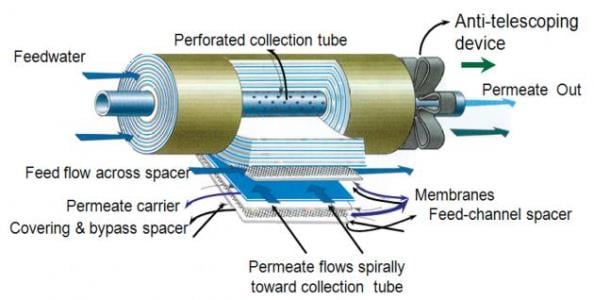
Most industrial RO units are based on the spiral-wound design. The membranes are manufactured in flat sheets, which are wound around a central core to produce a membrane element. They are, in essence, jelly-roll formations of RO membranes sandwiching fabric spacers and sealed on three sides. The fourth, open side is sealed around the perforations of a center core, usually of PVC. [1]
 Spiral-wound membrane.While RO units are virtually always equipped with inlet cartridge and/or bag filters for small particle removal, upstream suspended solids removal, especially when surface water is the raw source, is also necessary. One technique that has become increasingly popular for particulate removal is micro- or ultra-filtration (UF), which, in the case of UF, can remove from water particles as small as viruses.
This article will be based on a case study from the author’s experience at a large power plant where an aging clarifier and sand filter were replaced with a microfilter (MF).
Case History
This example comes from the water treatment system for an 800 MW supercritical steam generator. For more than 20 years, raw water pretreatment (the source is a human-made lake) consisted of conventional clarification followed by gravity sand filtration and reverse osmosis. Final polishing to produce the high-purity makeup for the steam generator was accomplished by cation-anion-mixed-bed ion exchange. The aging clarifier/sand filter combination could only deliver an effluent with at best a turbidity of 0.3 nephelometric turbidity units (NTU). Periodic upsets would drive the turbidity past 1 NTU. This necessitated change-out of the RO inlet cartridge filters every two to three weeks.
The age and outmoded style of the clarifier resulted in annual operation and maintenance costs greater than $100,000. That and the downstream effects on the RO unit offered the opportunity to perform a full-scale test of a microfilter for particulate removal.
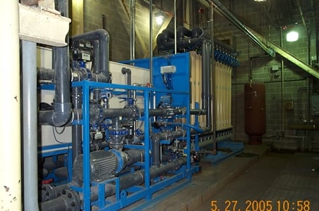
 Microfilter modules.Although most RO systems use spiral-wound membranes, micro- and ultrafilters are usually of the hollow-fiber configuration. What’s more, they are either of the pressurized style where water is forced through the membranes, or of the vacuum type where water is pulled through the membranes. This application used a pressure system in which each module contains thousands of spaghetti-sized hollow fiber tubes. To produce the 300-gpm flow sometimes required by the steam generator and its auxiliary systems, 24-membrane modules were necessary.
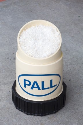
 Cutaway view of a module. Image source: Pall Corp.A cutaway view of one of the modules shows the membranes that are enclosed within.
In this particular design, the process operates via what may be considered as a combination of cross-flow and dead-end filtration. Raw water flows parallel to the outside membrane surfaces and filters to the inner hollow core, with particles remaining on the outside surface. Because all of the water during a process run is converted to permeate, the membranes accumulate solids that periodically must be backwashed and disposed. For this system, common procedure is a 20-minute process run followed by a roughly 60-second backwash (flow through the membranes during backwash is inside out) accompanied by an air scour process.
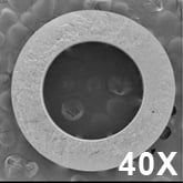
 Detailed view of a hollow-fiber membrane. Image source: Pall Corp.A common material of fabrication for these membranes is the robust compound PVDF (polyvinylidene fluoride). Thus, MF units can operate with a continuous feed of an oxidizing biocide like chlorine or bromine. Also, most modern units include a chemically enhanced backwash (CEB) system that periodically washes the membranes first with a dilute caustic/bleach solution followed by a rinse and then a dilute acid solution, most often citric acid. These chemicals help to remove accumulated organic and microbiological foulants, and, in the second step, iron oxide particulates.
From the first day this unit was placed in service until now (more than a decade of operation), the MF permeate turbidity has remained below 0.05 NTU. The benefits to the downstream RO were immediate and obvious. The interval for RO cartridge filter replacement went from roughly every three weeks to three months. In the 11 years of operation, not one membrane has failed, which shows this model’s durability.
However, as with other water treatment equipment, such systems must be handled with care. Units that treat raw water sources with large fluctuations in suspended solids (river water comes to mind first) can experience fouling that will shut down operation due to excessive differential pressure (typically termed “trans-membrane pressure”) in the membranes. And even with regular CEBs, periodic off-line cleanings are necessary to keep membranes in good condition. When possible, pilot testing of such units is recommended.
Is Clarification a Relic?
By no means has clarification become outdated with regard to RO and other industrial water pretreatment options. And this is becoming even more true as plant personnel elect to switch from fresh water supplies to less pristine makeup sources. Alternative sources may contain high hardness, alkalinity and silica, among other impurities, in which lime/soda ash softening is the most economical treatment method.
Potential users should be aware of developments in clarifier technology. To those with past knowledge of the process, the word “clarification” may bring back images of wide, tall circular or rectangular) vessels whose diameters for large applications sometimes reaching 80 feet or more. Such size was necessary to allow the correct coagulation and flocculation reactions to take place and produce a stable sludge for disposal. A common term for clarifier capacity is “rise rate,” which is the volumetric flow rate of the treated water per the surface area of the unit at the overflow weir. Common rise rates for these behemoth-like clarifiers were around 1 to 1.5 gpm/ft2.
Now, clarifiers are available with much higher rise rates, and thus much smaller footprints. One such system is known as Acti-Flow.
 (Click to enlarge.) Process schematic of an Acti-Flow clarifier. Image source: Veolia.One prominent feature of this process is its use of micro-sand to increase the solids content of the flocculation products that form in the clarifier mixing zones. This aspect, coupled with the inclined plate settling devices in the main body of the clarifier, can allow rise rates of perhaps 25 gpm/ft2, an increase over conventional clarification.
As the figure illustrates, the micro-sand is recovered and recycled by passing the sludge discharge through a hydrocyclone. The heavier sand particles break apart from the sludge and discharge through the hydrocyclone underflow. Meanwhile, the sludge is discharged to waste via the hydrocyclone overflow. Other clarifier designs based on advanced sludge recirculation techniques also are available to increase the rise rate over conventional clarification. These newer technologies help to address an important issue that plagued older units: process upsets due to variable water quality. Temperature changes or a sudden influx of suspended solids were often problematic with conventional units. The higher bulk of microsand or dense sludge blankets help to dampen these effects.
Future Discussion
Either by mandate or at times choice, municipal wastewater treatment plant effluent, is the required makeup source for many industrial plant, highlighting another area of possible concern. These supplies typically contain a number of impurities in much higher concentrations than fresh water, including ammonia, organic compounds, phosphorus (as phosphates) and suspended solids. Some of these contaminants (such as phosphates and suspended solids) can be removed by clarification. Others, however, and most notably ammonia, will essentially pass through conventional treatment systems untouched. The impurities can then cause problems in downstream equipment including makeup systems and cooling towers. One increasingly popular approach is biological treatment for ammonia and organics removal. A future article will address this topic.
https://insights.globalspec.com/article/1986/reverse-osmosis-pre-treatment-techniques-and-technology