Reverse osmosis (RO) has become popular for primary removal of dissolved ions in high-purity makeup water for such applications as electrical power generation by steam, semi-conductor manufacturing and pharmaceutical applications. What’s more, the technology is expected to maintain its popularity at new facilities around the world. However, many water treatment operators often do not understand important aspects about RO operation, and that proper pretreatment of the RO influent is essential to unit reliability and availability. This article explores important fundamentals of the RO process.
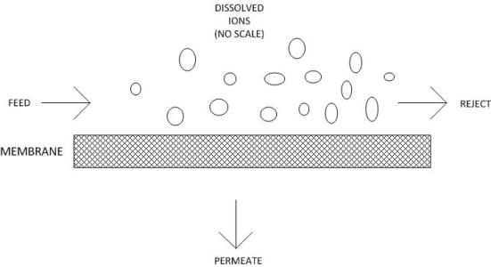
 Crossflow filtration.In conventional depth filtration, water flows perpendicularly to the filter medium. Particles are removed throughout the depth of the filter medium. Over time, the filter plugs with solids and must be replaced. Reverse osmosis operates via crossflow filtration, in which the feed water flows parallel to the membrane surface.
Operational Overview
Pressure that is applied to the feed works to force water through the membrane, producing the permeate stream. A significant portion of the feed water flows along the membrane, carrying rejected ions with it. This stream is known as the “reject” or “concentrate.”
The feature that makes RO unique compared to other filtration methods is its ability to remove dissolved solids down to the smallest ions. Although the passages within RO membranes are often referred to as pores, they more resemble maze-like tunnels. The passages range from 1 angstrom (10-8cm) to 10 angstroms in diameter. Because the pore diameters are so small, the molecular layer of water that attaches to the membrane surface and pore walls inhibits ions from passing through. Some ions and molecules (and particularly the monovalent ions sodium and chloride) still manage to leak through, so 100 percent efficiency is never possible.
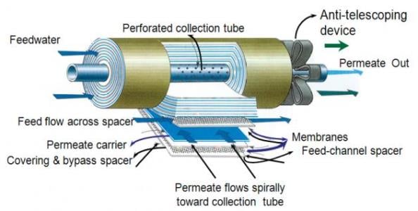
 Spiral-wound membrane. Image source: www.ivtnetwork.comBy far the most common RO membrane design is the spiral-wound configuration. These membranes are manufactured in flat sheets, which are wound around a central core to produce a membrane element. Purified water flows through the membrane along spacer material, and is collected in the central core. In a typical RO pressure vessel, several elements are placed in series and are sealed within the vessel.
 Outline of an RO pressure vesselInlet water enters the forward end of each element and flows to the opposite end. Purified water (permeate) passes to the central core of the element. Meanwhile the concentrate (reject) is collected and discharged at the element end cap. The feature of spiral-wound membranes that makes them most practical is the multiple wrap within an element. A common sheet surface area is 400 ft2, although greater area is possible if the spacer size is reduced. However, shrinking the spacer size makes the openings more susceptible to particulate fouling.
Complex Operation
A reverse osmosis unit has often been described as consisting of little more than a high-pressure pump, some pressure vessels and pipe. In truth, the operation is considerably more involved than this simple description suggests.
Spiral-wound membrane elements can come in several different sizes, but the most popular size is 8 inches in diameter by 40 inches in length. These are loaded in series into a pressure vessel with four, five or six elements per vessel being the most common. The rate at which water passes through the membrane is known as the flux and is measured in gallons per square foot per day (GFD). The general purity of the water in large part dictates the flux rate. A general guideline suggests:
- Surface Water: 8 to 14 GFD
- Well Water: 14 to 18 GFD
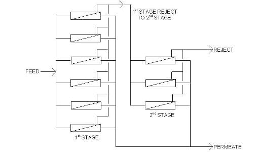
For normal surface and ground waters, each pressure vessel will produce about 50 percent purified water (permeate) and 50 percent concentrated water (reject or concentrate). At first blush, this does not seem efficient. However, the concentrate is often pure enough to be treated again at another 50/50 split to produce 75 percent capacity. The figure illustrates the generic design of a two-stage RO system. Sometimes even the second-stage concentrate can be treated in a third stage to deliver an overall RO output of greater than 80 percent.
RO elements that offer 99 percent or greater salt rejection are now available. Over time, however, membranes will degrade until, after two or three years of operation, salt rejection may have dropped by a percent or two. Even so, the RO still removes the bulk of dissolved ions. This benefit led to significant retrofit installations at many power plants in the 1980s and 1990s, where RO systems were placed ahead of existing demineralizers. This configuration extended demineralizer run lengths and cut down on regenerant costs.
It was not uncommon for regenerant chemical costs to exceed $100,000 per year for even a moderately sized (200 gpm) demineralizer. Operating costs for the RO pump (power), perhaps a small amount of anti-scalant feed, periodic chemical cleaning of the RO membranes and (reduced) regenerant chemical feed to the demineralizer are less. Membranes typically last 3-7 years, although longer life is possible. Membrane replacement costs may be a third of the original price of the RO.
Two-Pass Reverse Osmosis
At most new plants, specifications will call for a two-pass RO unit. In this design, the permeate from the first pass is treated in a second, two-stage RO pass. Thus the 99 percent-plus ion removal in the first pass is compounded by additional ion removal in the second pass. Typically with two-pass RO, just an additional bit of polishing either with mixed-bed ion exchange or electrodeionization (EDI) is needed to produce water suitable for the highest pressure steam generators or other applications.
 Diagram of a two-stage RO system.An often beneficial aspect of two-pass RO is its ability to remove carbon dioxide from makeup water. While conventional RO is excellent at removing dissolved ions, the process does not remove dissolved gases. If the inlet water is near or below a pH of 7, significant quantities of dissolved carbon dioxide (CO2) are most likely present. Injecting a small dose of caustic (NaOH) between the two RO passes converts the CO2 to dissolved bicarbonate alkalinity (HCO3-), which is then removed in the second RO pass.
Makeup Water Pretreatment
Even minor influx of suspended solids can cause problems in an RO unit, particularly in the lead elements. Thus, pretreatment must include particulate removal. An RO system is always equipped with inlet cartridge and/or bag filters for small particle removal, but primary pretreatment is also necessary. Earlier, clarification and multi-media filtration were the technologies of choice, but even these techniques may not be sufficient. More common today is micro- or ultra-filtration (also membrane-based technologies) that in some cases can remove particles as small as viruses from water. In fact, ultra-filtration (UF) has become increasingly popular in the potable water industry.
Although suspended solid pretreatment is critical for reliable RO operation, scale deposit prevention is also important. To understand why, refer to the earlier figures. As permeate is produced by the successive membranes, the reject ion concentration continually increases as the water passes from membrane to membrane. This increases the scaling potential. Calcium carbonate, calcium sulfate, silicates and other compounds can build up to a point where precipitation begins to occur.
While pretreatment may reduce the concentration of many scale-forming compounds, the remainder may still cause problems. Reputable membrane manufacturers have developed programs that will calculate the solubility limits for these salts in a particular application. The program will warn the user if any solubility limit is exceeded.
Because scale formation can quickly and often irreversibly degrade membrane performance, antiscalant feed is standard for industrial RO units. Common anti-scalants include polyacrylates and phosphonates. The chemicals function by sequestering cations or modifying crystal growth, such that adherent scales do not form. Just a few parts per million of the treatment is usually necessary to prevent heavy scaling.
Another critical point is that most RO membranes are now manufactured out of a polyamide material. A discussion of the material chemistry is beyond the scope of this article, but the critical point is that the material is immediately and irreversibly attacked by oxidizing biocides such as chlorine and bromine. Thus, if the raw water has been treated with any of these chemicals, they must be removed upstream of the RO unit.
RO Cleaning
Even with conscientious pretreatment, membrane performance will gradually decline over time, requiring periodic chemical cleanings. The need for cleaning can be most reliably detected by normalized flow monitoring (again programs can be obtained from reliable vendors), and should typically be performed once the flow has dropped 10 percent from the baseline value.
Because fouling is most prevalent on the concentrate side of the membrane, the chemical cleaning solution must be injected through the reject line. Cleaning solutions are prepared in an external tank and then circulated with a low-pressure pump through the pressure vessels. Only one stage at a time should be cleaned.
Common cleaning chemicals include citric acid for calcium carbonate and iron removal, a carbonate/EDTA chelant for calcium sulfate and alkaline phosphate/EDTA solutions for organically fouled resins. The strength of solution is usually between 1-2 percent. The solutions work better when warm, so the mixing tank is equipped with a heater to raise the temperature of the cleaning agent. In general, a temperature of 105°F is recommended.
https://insights.globalspec.com/article/1907/reverse-osmosis-fundamentals-for-process-industries