With perhaps the exception of the ongoing power plant construction boom in China and South Asia, conventional power plants are aging.
Worldwide, the average operating coal plant is approaching 40 years old. And in the U.S., only 10% of the coal fleet is younger than 30 years of age. Generating capacity is shrinking as operators reduce their greenhouse gas emissions to meet regulations. Coal plants are being shuttered and replaced by natural gas, wind, and other renewable generating resources.
For the conventional plants that remain, the need for boiler life life assessments becomes increasingly necessary to ensure both safe and reliable operations. As plants approach the end of their design life, boiler component and piping replacements become increasingly cost prohibitive.
To achieve effective assessments, it is critical to understand the potential failure mechanisms, their causes, and their impact. Various forms of degradation exert their toll on high temperature components to include creep, fatigue, creep-fatigue, carburization and high temperature corrosion, among others.
Creep
The end of useful service life among boiler componentry most often correlates to long-term overheating or (creep)-related failure(s). Creep can be defined as a time-dependent deformation at constant stress and elevated temperature. Metallurgical composition determines the temperature at which creep initiates. Regarding common alloys among boiler tubing, the table suggests threshold temperatures.
| Carbon Steel | 850
oF |
| Carbon + 1/2 Molybdenum | 900
oF |
| 1-1/4 Chromium-1/2 Molybdenum | 1025
oF |
| 2-1 /4 Chromium-1 Molybdenum | 1075
oF |
| Stainless Steel | 1300
oF |
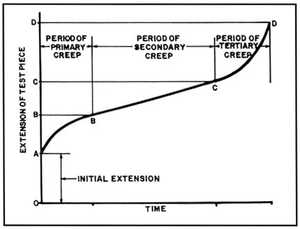
Elevated stresses and temperatures, below the high-temperature yield stress, enable permanent plastic deformation. The figure demonstrates a creep curve at constant loading. The length of a specimen is plotted against time. Four segments on the curve are of particular interest:
I. Points 0 to A signify the primary phase of rapid growth that is partially elastic in origin
II. Points A to B illustrate the region of decreasing deformation rate or “primary creep”
III. Points B to C demonstrate a constant creep rate. Referred to as “secondary creep,” its duration is somewhat linear and can endure several decades
IV. The final portion of the creep curve from points C to D is the “tertiary creep” stage where rapid and exponential deformation occurs to culminate in failure
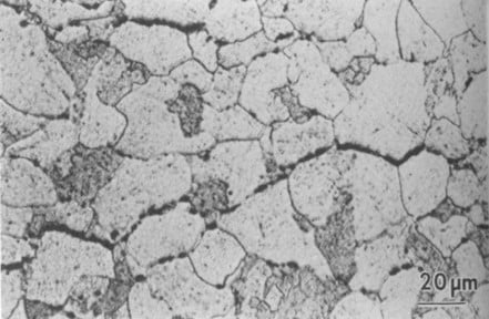
Metallurgical grain-boundary movements permit creep deformation as adjacent grains or crystals slide against each other. An important microstructural feature of a creep failure is the insignificant deformation to distinct grains along a crack’s edge. Creep evidence is not apparent until the secondary creep phase of the figure where microstructural voids emerge.
 Schematic creep curve. Image credit: Babcock & WilcoxWith time, more voids appear, grow and link to form cracks several grains in length. Failure manifests in rupture by tensile overload as the effective wall thickness becomes too thin to retain steam pressure.
Because adjacent grain-boundary movements enable creep deformation, it follows that smaller grain sizes display increased total grain boundary surface area and a reduced creep strength as a consequence. This explains why creep-resistant materials, such as austenitic stainless steels, require larger grain sizes by code. Additional microstructural alterations accompany creep at elevated temperatures to include graphitization of carbon steels and spheroidization among low-alloy steels.
Creep failures are characterized by:
· Bulging or blisters in the tube
· Thick-edged fractures often with very little obvious ductility
· Longitudinal "stress cracks" in either or both ID and OD oxide scales
· External or internal oxide-scale thicknesses that suggest higher-than-expected temperatures
· Intergranular voids and cracks in the microstructure
Root Causes
Although creep is anticipated and inevitable among boiler components exposed to the highest temperatures such as ferritic superheaters and reheaters, its progression is accelerated under adverse conditions. The chief cause of premature failure is the gradual increase in tube-metal temperatures of 25 to 75oF from the formation of the steam-side iron oxide scale, a natural reaction of steam and steel.
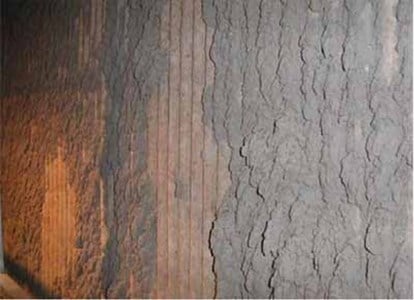
 Boiler tube fouling.This oxide scale thickness depends upon operating temperatures and their duration. Steel tubing has a thermal conductivity about 20 times greater than oxide scale. To the extent the oxide scale layer increases, it insulates the outer tube metal from necessary steam cooling. It prompts elevated temperatures to produce increased creep deformation rates, internal corrosion and hasten further oxidation. Consequently, thinner tube wall thickness accelerate the onset of creep failures.
Variations in tube metal temperatures induce early failures. Plant operators gage tube temperatures primarily through thermocouples. These thermocouples are located on boiler tubing adjacent to their corresponding headers within the boiler penthouse.
Unfortunately, they are located on only a small fraction of total tubing surface area. Thus, the law of averages leaves the plant operator oblivious to localized tube overheating. Also, the tubes at this location are not “gas touched,” therefore heat transfer is not occurring. So just upstream of the tube metal thermocouple, where active heat transfer is taking place, the tube outer skin temperature may be 50-100°F higher than the thermocouple reading.
Even though creep failures are expected when operating at design conditions, deviancies from these parameters will induce untimely failures. Steam temperatures constantly fluctuate from individual tube to tube, and design parameters tolerate these oscillations. Still, when the variability of temperatures is larger than expected, tubes subjected to the highest temperatures will fail sooner than expected.
Boiler “fouling” introduces additional challenges for localized overheating. Fouling generally refers to ash accumulation impacting the convection pass after the gases exit the furnace. Ash cinders form on the leading edges of the superheater and reheater tubes, especially among coals with lower ash fusion temperatures. Despite cleaning methods such as sootblowing, problematic fouling often accumulates to the extent where heat transfer is restricted among sections of tubing. Consequently, the gas path is diverted around the remaining tubing.
 Intergranular creep void alignment.In addition to coal ash corrosion due to increased gas velocities, these remaining tubes are subjected to increased heat.
The Larsen-Miller Parameter
Creep/stress rupture data for high-temperature boiler componentry is often plotted using log stress to rupture versus a combination of log time to rupture and temperature. The Larson-Miller parameter is a means of predicting the lifetime of material vs. time and temperature. The value of the parameter is usually expressed as:
(LMP) = (T + 460) (20 + Log t) where T is the temperature in Fahrenheit and t is the time in hours.
If a stress rupture failure is expected to occur at 250,000 hours (≈ 28.5 years), when the tube design metal “upper limit” is 1,100°F, the LMP is 39,600.
39,600 = (1,100 + 460) (20 + Log 250,000)
· If the tube metal temperature is raised to 1,120°F (20°F above the design “upper limit” for thousands of hours), the time to failure is 116,000 hours (54% life reduction ≈ 13 years)
· If the tube metal temperature is raised to 1,150°F (50°F above the design “upper limit” for thousands of hours), the time to failure is 39,500 hours (85% life reduction ≈ 4.5 years)
· If the tube metal temperature is raised to 1,200°F (100°F above the design “upper limit” for thousands of hours), the time to failure is 7,200 hours (97% life reduction ≈ 10 months)
Four chief ways exist to prevent creep in boiler components: utilize higher melting temperature metals, make use of materials with greater grain size, employ alloying of creep-resistant material, and apply intelligent design to reduce the contributing factors of creep.