Introduction
In any heat transfer equipment such as a boiler or Heat Recovery Steam Generator (HRSG), the exit gas temperature determines the amount of energy recovered from the flue gas stream, which is indicative of efficiency. Hence efforts are often made to lower this temperature as much as possible taking into consideration cost effectiveness and low temperature corrosion concerns. In a conventional steam generator such as a package boiler, the exit gas temperature is independent of steam pressure. With say a 230 F feed water temperature, an exit gas temperature of about 300 F can be easily achieved using an economizer as the heat recovery equipment. However in a gas turbine HRSG, due to thermodynamic reasons, the exit gas temperature is a function of inlet gas temperature, feed-water temperature and steam pressure. The low exhaust gas temperature from gas turbines, typically ranging from 900 to 1050F, generates less steam on unit gas mass basis in the HRSG evaporator compared to a package boiler. On the other hand, in a steam generator or package boiler, the flue gas stream is cooled from adiabatic combustion temperature of 3300 F and hence generates a large amount of steam on unit gas mass basis. Table 1 shows the gas/steam ratio of HRSGs and steam generators. The small ratio of steam to gas flow in a HRSG is not adequate to cool the exhaust gases in the economizer, resulting in a high exit gas temperature. Also it can be shown that higher the steam pressure, higher the exit gas temperature and vice versa. However various options are available for lowering the exit gas temperature, which improves the HRSG efficiency and these are examined in this article.
Table 1: Gas inlet temperature vs Steam generation in HRSGs and steam generatorsType of HRSG gas inlet temp Gas/steam
Unfired 850-1000 7 to 5.5
Supplemenatry fired 1000-1700 5.5 to 2.5
Furnace fired HRSG 1700-3200 2.5 to 1.2
Steam generator* 3300-3400 1.2 to 1.3
[* typical oil or gas fired steam generator]
HRSG temperature profiles
Fig 1 shows a simple gas turbine HRSG consisting of a superheater, evaporator and economizer. The exhaust gas from the gas turbine enters the HRSG at a temperature of Tg1. Steam is generated at a temperature of ts2 using feed water at tw1. Two important variables determine the temperature profiles and steam generation, namely Pinch point and Approach point.
Pinch point is the difference between the gas temperature leaving the evaporator and saturation temperature=Tg3-ts
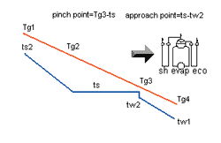
Fig 1: HRSG temperature profiles
Approach point is the difference between saturation temperature and feed water temperature entering the evaporator= ts -tw2.
Pinch and approach points cannot be arbitrarily selected. In an unfired HRSG, minimum pinch and approach points range from 10 to 20 F depending on economic considerations. A low pinch or approach point naturally increases the surface area required for the evaporator and economizer and thus the HRSG cost. A large value for these variables decreases the amount of energy recovered and hence a balance has to be struck.
The energy recovered from the superheater and evaporator=Q12=WgCp(Tg1-Tg3)xhl=Ws(hs2-hw2)
The energy recovered from the complete HRSG=Q13=WgCp(Tg1-Tg4)=Ws(hs2-hw1)
In the above equations, blow down was neglected.
Wg, Ws=gas flow and steam generation, lb/h
Cp=gas specific heat, Btu/lbF
hs2=enthalpy of steam, Btu/lb
hw1,hw2=enthalpy of feed water entering and leaving economizer, F
Tg1,Tg2,Tg3,Tg4=gas temperatures at various surfaces as shown in Fig 1, F
hl=heat loss factor, typically 0.99 to 0.995
Neglecting variations in gas specific heats we have from the above equations:
(Tg1-Tg3)/(Tg1-Tg4)=(hs2-hw2)/(hs2-hw1)=X
where X is a function of steam parameters. For steam generation to occur, two conditions must be satisfied: Tg3>ts and Tg4>tw1
If the pinch point is arbitrarily selected, then it is likely that Tg4 can be lower than tw1; if the approach point is arbitrarily selected, then it is likely that Tg3 can be lower than ts. These situations are referred to as temperature cross conditions from thermodynamic view point.
Thus one cannot assume an exit gas temperature and determine the steam generation. A temperature profile analysis must be done in the unfired mode as shown below.
Evaluating Steam Generation and Temperature profiles in a HRSG
Example: A HRSG generates 600 psig, 750 F steam using feed water at 230 F. Exhaust gas flow is 160,000 lb/h at 950 F.% volume CO2=3, H2O=7, N2=75, O2=15. Calculate the unfired steam using 25 degree pinch and 20 degree approach points. Use a heat loss factor of 0.98.
Solution: Assume 10 psi pressure drop in the superheater. The drum pressure is 610 psig and the saturation temperature is 492 F. The gas temperature leaving the evaporator=492+25=517 F. The feed water temperature entering evaporator or leaving economizer is 492-20=472 F.
The energy absorbed by superheater and evaporator= 160,000 x 0.27 x 0.98 x (950-517)=18.33 MM Btu/h. In this expression, 0.98 refers to the 2 % heat loss in the HRSG system and 0.27 the specific heat of the gas at the average temperature of 734 F.
The enthalpy absorbed by steam=(1378.9-455.4) Btu/lb, where 1378.9 and 455.4 refer to enthalpies of steam at 600 psig, 750 F and at water at 472 F. Neglecting blow down, we have the steam production as: 18.33x10⁶/(1378.9-455.4)=19,850 lb/h
The energy absorbed in the superheater= (1378.9-1202.8) x 19,850=3,495,600 Btu/h
The gas temperature drop across the superheater=3.495x10⁶/(160,000x0.98x0.28)=79 F
Thus gas temperature leaving the superheater= 950-79=871 F
The energy absorbed by economizer=19850 x (455.4-199.7) = 5.076x10⁶ Btu/h, where 199.7 is the enthalpy of the feed water at 230 F.
The gas temperature drop across economizer=5.076x10⁶/(160,000x0.98x0.26)=125 F. Thus HRSG exit gas temperature=517-125=392 F
The total energy absorbed by steam=23.4 MM Btu/h
This calculation is referred to as the design mode.
It may be seen that the exit gas temperature is rather high. With lower pinch and approach points, we could bring it down a little to around 370 F but not to 300 F range. Thus unfired single pressure HRSGs are not very efficient particularly at high steam pressures. The exit gas temperature will be higher at higher steam pressures. Table 1 shows the results of calculations for various steam pressures.
Table 1: Exit gas temperature from unfired HRSG
|
Pressure |
Steam tem,F |
Sat tem, F |
X |
Exit gas,F |
|
100 |
Sat |
338 |
0.904 |
300 |
|
150 |
Sat |
366 |
0.8754 |
313 |
|
250 |
Sat |
406 |
0.8337 |
332 |
|
400 |
Sat |
448 |
0.7895 |
353 |
|
400 |
600 |
450 |
0.8063 |
367 |
|
600 |
Sat |
490 |
0.74 |
373 |
|
600 |
750 |
492 |
0.7728 |
398 |
(based on 15 F approach point,20 F pinch point and 900 F gas inlet temperature and no blow down. Feed water temperature=230 F)
- It can be easily seen that higher the steam pressure, higher the exit gas temperature. This is due to the fact that higher the steam pressure, higher the saturation temperature of steam and higher the gas temperature leaving the evaporator. Hence less energy is available between the gas inlet temperature and gas temperature leaving the evaporator and the resulting flow through the economizer is not adequate to cool the exit gas temperature to a low level.
- Higher the steam temperature, higher the exit gas temperature. This is again due to the fact that less steam is generated if it is superheated (due to the higher enthalpy absorbed by steam) and the resulting low flow through the economizer is not adequate to cool the exhaust gases to a low exit gas temperature.
- Higher the gas inlet temperature, lower will be exit gas temperature. For example, if the inlet temperature is 1000 F instead of 900 F, the exit gas temperature for the case of 600 psig, 750 F steam is: 1000-(1000-512)/.7728=369 F versus 398 F. This is due to the simple fact that more energy is available between the gas temperatures entering the HRSG and leaving the evaporator, which generates more steam, which in turn results in more water flow through the economizer; the larger heat sink at the economizer can cool the gases further. It may be shown similarly that lower the gas inlet temperature, higher the exit gas temperature from the HRSG. This is one of the reasons that part load operation of gas turbines is not generally a good idea.
- Lower the feed water temperature, lower will be exit gas temperature. However one can to consider condensation of water vapor on economizer surfaces if the inlet temperature is below the water dew point.
We mentioned earlier that the exit gas temperature and pinch and approach points cannot be arbitrarily selected and an analysis similar to that above should be done to establish temperature profiles else there will be temperature crossings. To illustrate this point, a few examples are given.
Example: Can we obtain a stack temperature of 300 F with 900 F gas inlet temperature and with steam parameters of 600 psig,750 F and 230 F feed water?
We note from Table 1 that 398 F is the exit gas temperature. With minor improvements in pinch and approach points, the exit gas temperature can be lowered slightly but not to 300 F level. Let us see what happens if we did so.
X=0.7728=(900-Tg3)/(900-300) or Tg3=437 F! The gas temperature leaving the evaporator cannot be lower than the saturation temperature of 492 F; this indicates a temperature cross situation. Hence it is a thermodynamic issue and no amount of surface area at the evaporator or economizer can lower the exit gas temperature below the level of 398 - 380 F.
Example: Can we have a pinch point of 20 F when the gas inlet temperature is say 1500 F?
Tg3=512 F at 600 psig. (1500-512)/(1500-Tg4)=0.7728 or Tg4=221 F, which falls below the feed water temperature. Hence a large pinch point and a large approach point is associated with high inlet gas temperatures.
Predicting off-design performanceIn order to evaluate the temperature profiles in the fired mode or other off-design cases, a HRSG simulation analysis should be done[1]. This analysis estimates the (UA) value of each surface and corrects it for the off-design or fired conditions for the effects of gas flow, gas analysis and temperature.[U=overall heat transfer coefficient and A=surface area].Then using the NTU (Number of Transfer Units)method, one arrives at the performance. In the off-design mode the pinch and approach points fall in place. There is only one design mode analysis but there can be numerous off-design cases.A software is required to perform this complex analysis, particularly if the HRSG has multiple pressure levels and has a complex arrangement of heating surfaces. Note that simulation analysis does not require the physical design of the HRSG as UA is taken as a single entity, which can be obtained from the equation Q=UADT, where Q=energy transferred to the surface and DT is the log-mean temperature difference.
Once we have the HRSG performance in various modes of operation such as unfired, fired, part load etc, the next question is: How can we improve the efficiency of a HRSG or lower the exit gas temperature?
Options to improve HRSG efficiency
There are a few options to improve the efficiency of a HRSG. These could be combined or used in isolation. The ideal option varies from case to case based on plant operating period, cost of fuel and electricity and initial investment cost.
- Multiple pressure steam generation
- Optimizing arrangement of heating surfaces
- Auxilliary firing
- Use of secondary surfaces such as condensate heater, de-aerator or heat exchanger
- Using low pinch and approach points for the HRSG evaporator
Multiple pressure steam generation
As seen earlier, in an unfired HRSG the exit gas temperature is rather high and the situation worsens if the steam pressure is increased. Hence in order to lower the exit gas temperature from the HRSG, additional steam may be generated at a lower pressure as shown in Fig 2. In this design, the high pressure stage is followed by the low pressure system. Using the HRSG simulation program [1].the design temperature profiles were obtained. The figure shows a HRSG generating 39,500 lb/h of high-pressure steam at 800 psig/750 F and 6270 lb/h low pressure steam at 100 psig. The exit gas temperature is 340 F.
Rearranging heat transfer surfaces
Though the option discussed above is better than a single pressure system, one can improve the energy recovery through rearrangement of heating surfaces. The heat sink or the economizer, in Fig 2 is not a large one, basically handling the water flow of the low-pressure evaporator. If the water flow through this can be increased somehow, we can cool the exhaust gases further. The simplest way is to use the common economizer concept as shown in Fig 3. Here the feed-water through the economizer feeds both the high and low-pressure evaporators, thus handling much larger amount of flow. This larger heat sink cools the exhaust gas to 281 F versus 340 F in the earlier case. We are able to generate more low-pressure steam.
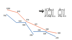
Fig 2: HRSG temperature profiles using separate modules
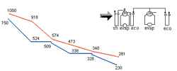
Fig 3: HRSG temperature profiles using common economizer concept
Auxilliary firing
Auxilliary firing of turbine exhaust gases is the simplest way to improve the efficiency of a HRSG. In a gas turbine, unlike a steam generator, the exhaust gas flow remains constant and adding fuel alone without adding air increases the exhaust gas temperature. The exhaust gas typically has 14 % volume of oxygen and hence is capable of being fired to about 3000 F without additional air. The relation between oxygen consumption and fuel input to a HRSG is given by the simple relation [1]: Q=58.4WO
Where Q=heat input in MM Btu/h on LHV basis
W=gas flow, lb/h and O is the oxygen consumption in % volume.
Let the exhaust gas flow=100,000 lb/h at 900 F with the following analysis: CO2=3,H2O=7,N2=75 and O2=15 by volume. If the gas inlet temperature is 900 F and is raised to 3000 F, the fuel required can be shown to be 74 MM Btu/h. This lowers the oxygen content by about 12.3 % and hence 2.7 % oxygen still remains in the exhaust gases. Thus a lot of energy can be added to the exhaust gases, which in turn generates steam in the HRSG. The exit gas temperature is also lowered due to the larger heat sink in the form of economizer. In fact, it can be shown that the efficiency of fuel input is nearly 100 % or all of the fuel goes into generating steam. In a conventional boiler, it is a well known fact that increasing the excess air decreases the boiler efficiency. In a HRSG,the excess air is decreased by addition of fuel, which increases the efficiency. Also, we have a lower exit gas temperature, which also contributes to the efficiency improvement.
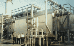
Fig 4: Furnace fired HRSG in a cogeneration plant
Fig 4 shows the arrangement of a furnace fired HRSG capable of being fired to adiabatic combustion temperature. It has water cooled membrane walls, a furnace section, followed by a screen section, a two-stage superheater and an evaporator with an economizer. Fig 5a, 5b show gas/steam temperature profiles of a HRSG in unfired and fired modes. The HRSG was designed in the unfired mode and its performance simulated in the fired mode. The printouts from the simulation program also show the HRSG efficiency using ASME PTC 4.4 method. Note the change in the pinch point, approach point and the exit gas temperature in the fired mode. The additional fuel input of 27.83 MM Btu/h adds 28.5 MM Btu/h to the steam, which is indicative of the 100 % plus efficiency of fuel utilization in the fired mode. In fact it can be shown that in a cogeneration plant, it makes more sense to generate additional steam in the HRSG rather than in the package boiler, as the efficiency of steam generation is only about 92 to 93 % (LHV) in a boiler versus 100 % in a HRSG.
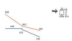
Fig 5a: HRSG temperature profiles in the design,unfired mode
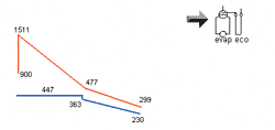
Fig 5b: HRSG temperature profiles in off-design, fired mode
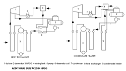
Fig 6: Secondary surfaces to improve HRSG efficiency
Secondary surfaces to improve efficiency
Fig 6 shows the arrangement of various secondary surfaces to improve the energy recovery process. The de-aerator coil supplies steam for de-aeration and also cools the exhaust gases. The condensate heater preheats the make up water before entering the de-aerator and thus reduces the steam for de-aeration. The heat exchanger option increases the energy recovered from the exhaust gases and also reduces the de-aeration steam.
Using low pinch and approach points
If secondary surfaces or low pressure steam is not required, one may use low pinch and approach points to maximize steam generation. However this increases the HRSG evaporator and economizer surfaces and hence the cost. An economic evaluation may be done to arrive at the optimum pinch and approach points.
Conclusion
Efficiency of an unfired single pressure HRSG is low and can be improved using several methods as discussed above. Though the cost of the HRSG increases, the payback is quick and well worth consideration, particularly when the fuel cost is on the rise. HRSG simulation is a valuable tool that may be used to evaluate the performance of HRSGs in various modes of operation to determine if the HRSG design can be optimized. It also helps to arrive at the gas/steam temperature profiles in a HRSG, which is basic to understanding and improving the HRSG performance.
References
1.V.Ganapathy, “Waste Heat Boiler Deskbook”, Fairmont Press
2.V.Ganapathy, “HRSGs-Understanding the basics”, Chemical Engineering Progress, Aug 1996.
3.V.Ganapathy, “Efficiently generate steam from cogeneration plants”, Chemical Engineering, May 1997
Author Information
V.Ganapathy is a Heat Transfer Specialist with ABCO industries, Abilene, Texas, where he is responsible for process engineering of package boilers and heat recovery boilers. He holds a Bachelor’s and Masters degree in Mechanical Engineering. Ganapathy is the author of over 200 articles and papers on boilers, heat recovery and steam generation and has authored four books. He has also contributed several chapters to the Encyclopedia of Chemical Processing and Design. He can be reached at vganapathy@abcoboilers.com