2.4. Process Description of the Simulated NGCC Power Plant
As shown in Figure 7, a 600 MW-natural gas combined cycle (NGCC) with a flue gas recirculation ratio of 0.42 is simulated in this study. 23.81 kg/s of natural gas (CH4 = 93% mol) is supposed to be available in a battery limit of the plant at 3.1 MPa and 25˚C and 449.2 kg/s of fresh air at design condition is compressed up to 3.1 MPa in a three stages compressor with intercooling. NG mixes with primary air in the combustor and it is assumed that combustion is complete and all the carbons in NG convert to CO2. The temperature of the combustion gases is 2100˚C. Secondary air is mixed with recirculated flue gas to cool the combustion
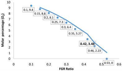
Figure 5. Effects of FGR ratio on the content of O2 in the flue gas.
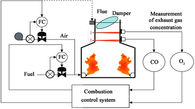
Figure 6. CO and O2 control system for combustion [15] .
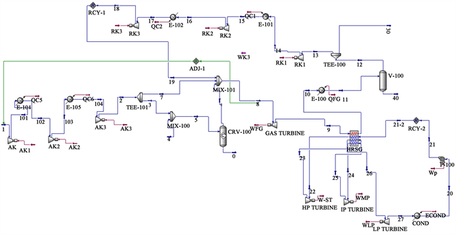
Figure 7. Simulated Natural Gas Combined Cycle (NGCC) power plant process flow sheet.
gases until 1300˚C before entering the turbine. The exhaust gases leave the gas turbine at atmospheric pressure and 618˚C. The flue gas enters to HRSG in order to produce 55 kg/s of steam at three levels of pressure: high pressure (HP) steam (173 Bars, 600˚C), an intermediate pressure (IP) steam (65 bars, 565˚C), and a low pressure (LP) steam (2 bars, 350˚C) with double reheat. The medium pressure steam (IP) is heated from 438˚C to 565˚C and the low pressure steam (LP) is heated from 206˚C to 350˚C. After leaving the Heat Recovery Steam Generator (HRSG), the flue gas is cooled from 67˚C to 40˚C in order to remove water in the separator V-100 and 42% of the flue gas is recycled. The pressure of the recycled gas will increase from 110 kPa to 3.1 MPa using three stages compressor with intercooling at 40˚C and mixed with secondary ambient air.
2.5. Simulation of the Effects of FGR Ratio on the Energies Streams of the Power Plant
The impact of the recirculation of flue gas on the power input or output of the different equipment of the power plant are investigated. The objective is to compare the performance of each equipment of the plant with flue gas recirculation ratio of 0.42 to its performance without flue gas recirculation.
2.5.1. Compressors
In this study, fresh air at15˚C (Design conditions) is compressed up to 3.1 MPa in three stages-compressor with intercooling at 40˚C. The pressure of the recycled gas is also increasing from 110 kPa to 3.1 MPa using three stages compressor with intercooling at 40˚C. An adiabatic efficiency of 85% is selected for both compressors [16] . The effects of the flue gas recirculation ratio on the energy consumption of the compressors of ambient air and flue gas are represented in Figure 8.
As expected, the flue gas recirculation ratio increases the energy needed for the compression of the recycled flue gas and decreases the energy consumption of the compressor of ambient air. Because both compressors work under same operating conditions and the main component of flue gas and atmospheric air is nitrogen, the two slopes have similar values.
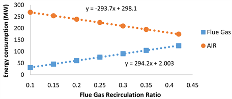
Figure 8. Effects of FGR ratio on energy consumption of compressors.
2.5.2. Heat Recovery Steam Generator (HRSG)
Currently many of the steam turbines in Combined Cycle plants operate at high pressure (HP) circuit. To absorb more heat two additional evaporators are used. One operating at intermediate pressure (IP) circuit. The second at lower pressure (LP) circuit. This together with economizers and superheaters in these pressure levels enable absorbing more heat. According to the simulation outputs, the temperatures of the exhaust gas entering and leaving the heat recovery steam generator (HRSG) are respectively 618˚C and 67˚C. The steam cycle contains a high pressure (HP) steam (173 bars, 600˚C), an intermediate pressure (IP) steam (65 bars, 565˚C), and a low pressure (LP) steam (2 bars, 350˚C) with double reheat. The medium pressure steam (IP) is heated from 438˚C to 565˚C and the low pressure steam (LP) is heated from 206˚C to 350˚C. The heat recovery steam generator (HRSG) was simulated without heat loss and the effects of flue gas recirculation on the heat available to produce steam are shown in Figure 9.
According to the simulation results, flue gas recirculation has positive effects on the amount of heat available in the HRSG. For the optimum value of 0.42, the heat available in the heat recovery steam generator is 3.1% higher than heat available without flue gas recirculation. For the same temperature difference and the same mass flow rate, the positive effects of flue gas recirculation could be explained by the fact that flue gas has a specific mass heat capacity (1.124 kJ/kg∙˚C) higher than the specific mass heat capacity of air (1.01 kJ/kg∙˚C).
2.5.3. Steam Turbine & Pump
The steam cycle contains High Pressure, Intermediate Pressure and Low pressure stages with two reheats. The adiabatic efficiency of the turbine, generator, and condensate pump are selected as 75%, 94%, 65% respectively [17] . The effects of the flue gas recirculation on the production of electricity by the steam turbine and the energy consumed by the pump are shown in Figure 10.
In concordance with Figure 9, Figure 10 indicates that flue gas recirculation has positive effects on the energy produced by the steam turbine. On the other
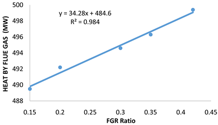
Figure 9. Effects of FGR ratio on the heat available in the HRSG.
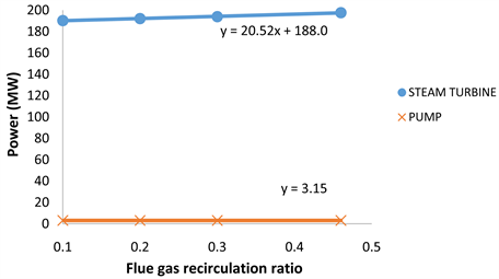
Figure 10. Effects of FGR ratio on energy of the steam cycle.
hand, it has no effects on the energy consumption of the water pump of the steam cycle. Based on simulation results, for a value of FGR of 0.42, the steam cycle produce 4.2% more power than the steam power plant with no flue gas recirculation.
2.5.4. Gas Turbine
The net output of gas turbine increases with the temperature of the exhaust gas but it is limited by the metallurgical limitation for the gas turbine being utilized. The effects of Flue Gas Recirculation (FGR) ratio on the temperature of the exhaust gas leaving the combustor are therefore investigated and the simulation results are shown in Figure 11.
Figure 11 shows that the flue gas recirculation decreases linearly the temperature of the flue gas entering the gas turbine. However, recirculated flue gas has a temperature (215˚C) higher than the temperature of fresh air (190˚C). This cooling effect could also be explained by the fact that flue gas absorb more heat because its specific mass heat capacity (1.124 kJ/kg∙˚C) is 11.3% higher than the specific mass heat capacity of fresh air (1.01 kJ/kg∙˚C). In a gas turbine, the blades have a metallurgical limitation and the temperatures could vary from 800˚C to 1700˚C depending on their materials and whether or not they have cooling systems [10] . According to Figure 12, The NGCC type is located between the D and F types with a flue gas temperature around 1300˚C.
Based on the information in Figure 12, the temperature 1300˚C is therefore used in this study as the metallurgical limitation of the turbine. The effects of flue gas recirculation on the power generated by the gas turbine are shown in Figure 13.
In concordance with Figure 11, the FGR ratio decreased the power produced by the gas turbine. However, the relationship has two different slopes. At values of FGR ratio lower than 0.25, the effects of the recirculation of flue gas on the power output of the gas turbine are negligible. For values of FGR ratio higher than 0.25, the negative effects of the recirculation of the flue gas are more visible.
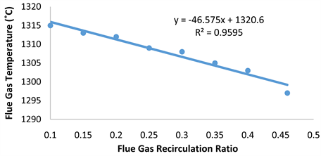
Figure 11. Effects of FGR ratio on the temperature of flue gas.
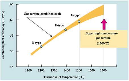
Figure 12. Turbine inlet temperature and combined plant efficiency [16] .
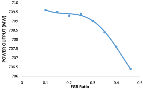
Figure 13. Effects of FGR ratio on the power generated by the gas Turbine.
2.6. Simulation of the Effects of FGR Ratio on the Overall Efficiency of the Power Plant
Natural Gas Combined Cycle (NGCC) power generation is an energy conversion system of generating electric power that combines gas turbine power generation (CTG) with steam turbine power generation (STG). The thermodynamic power cycles can be categorized as gas cycles and steam cycles. Gas turbines operate using the principles of the Brayton cycle. The isentropic efficiency (ηiso) of the Brayton cycle can be expressed in terms of the temperatures and pressures entering (P1 & T1) and leaving (P2, T2) the compressor:
ηiso=1−T1T2=1−(P1P2)k−1k">


 ηiso=1−T1T2=1−(P1P2)k−1k(6)
where k is the specific heat ratio. Based on Equation (6), increasing the temperature of the stream leaving the compressor or increasing the pressure ratio will enhance the efficiency of the gas turbine. In this investigation, fresh air enters the compressor at design conditions of 15˚C and the temperature of the exhaust gas is limited to 1300˚C. Based on these operating conditions, the isentropic efficiency of the gas turbine is 0.82. This value was selected as the adiabatic efficiency of the gas turbine for the simulation of the natural gas combined cycle. The corresponding power output of the gas turbine is 708.5 MW. The compressors of fresh air and recirculation of flue gas consume respectively 174.21 MW and 125.89 MW. The net output of the gas turbine is equal to 408.4 MW.
The overall efficiency of the gas turbine could be estimated by the following equation:
η=WnetoutputmNG×LHV">


 η=WnetoutputmNG×LHV(7)
where Wnet output is the difference between the energy produced and the energy consumed by the different equipment of the combustion turbine generator (CTG), mNG is the mass flowrate of natural gas and LHV is the low heating value of natural gas. Using the Low heating value (LHV) and the mass flow rate of the natural gas (46.7 MJ/kg and 23.81 kg/s), the efficiency of the gas turbine is equal to 36.1%. This value corresponds to the efficiency of the Open Cycle Gas Turbine (OCGT). The hot stream (exhaust gas) with a temperature of 617˚C will be used to produce more electricity by generating steam in the Heat Recovery Steam Generator (HRSG). Steam turbine in a combined cycle powerplant operates using the principles of the Rankine cycle. Like the Brayton cycle, the ideal Rankine cycle operates on four internally reversible processes. The theoretical maximum efficiency of a Rankine cycle is the Carnot efficiency given in Equation (8).
ηCarnot=1−TColdTHot">


 ηCarnot=1−TColdTHot(8)
In this investigation, the highest temperature is the temperature of the steam entering the HP turbine at 585˚C and the cold temperature is the temperature of water leaving the condenser at 30˚C. Based on these data, the maximum efficiency of the steam cycle is 64.7%. The thermal efficiency of a Rankine cycle is lower than that of a Carnot cycle operating between the same temperature levels. This is primarily because of the fact that the energy transfer as heat in the boiler does not take place at constant temperature in the Rankine cycle. The purpose of a reheating cycle is to remove the moisture carried by the steam at the final stages of the expansion process and improves the efficiency of the cycle, because more of the heat flow into the cycle occurs at higher temperature.
Based on Figure 14, the thermal efficiency of the Rankine cycle with reheat is given by Equation (9):
η=(h1−h2)+(h3−h4)+(h6−h5)(h1−h6)+(h3−h2)=Wnet-outQin">


 η=(h1−h2)+(h3−h4)+(h6−h5)(h1−h6)+(h3−h2)=Wnet-outQin(9)
The power produced by the three turbines is equal to 32.74 MW (HP), 114.3 MW (IP) and 66.8 MW (LP). The pump consumes 3.15 MW. Based on the low heating value of the natural gas, the efficiency of the steam turbine is equal to 18.9%.
Because of the complementary temperature ranges of the Brayton GT cycle (1300˚C - 618˚C) and the Rankine steam cycle (618˚C - 67˚C), natural gas combined cycle (NGCC) can produce significantly improved thermodynamic cycle efficiency (Figure 15).
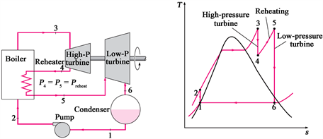
Figure 14. Ideal reheat rankine cycle [18] .
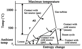
Figure 15. T-S diagram of NGCC cycle [19] .
The net output of the NGCC power plant without flue gas recirculation and with a FGR ratio equal to 0.42 are respectively 610.89 and 618.57 MW. Based on the Low heating value (LHV) of the natural gas, the overall efficiency of the power plant increased by 1.1% from 57.5% from to 58.2%.
3. Summary of the Simulation Results
First, the molar compositionS of the flue gas without recirculation and with a circulation ratio of 0.42 are compared in Table 3. The molar composition of carbon dioxide and oxygen in the flue gas with a FGR ratio of 0.42 is close to the requirements of the composition of flue gas needed for an effective absorption of the CO2 (CO2 ≥ 10% and O2 < 5%).
Secondly, the simulation results of the effects of the flue gas recirculation on the power input/output of the different equipment of the power plant are summarized in Table 4.
4. Discussion and Conclusions
The first goal of this work was to simulate a natural gas combined cycle (NGCC) power plant for a production of 620 MW of electricity. The needed mass flow rates of natural gas and ambient air with 100% excess air were estimated by preliminary calculations assuming complete combustion of the natural gas. Since
Table 3. Molar composition of flue gas without recirculation and with a FGR ratio of 0.42.
Table 4. Summary of simulation results.
natural gas-fired power plants with Carbon Capture and Storage (CCS) are expected to play a significant role in order to reduce carbon dioxide emissions from the power generation sector, the effects of flue gas recirculation on the concentrations of CO2 and O2 in the flue gas leaving the simulated power plant were investigated. The objective was to reach a molar percentage of CO2 equal to 10%. Moreover, in order to reduce technical problems due to amine oxidative degradation, the molar percentage of O2 in the flue gas should also be limited to 5%. The recirculated flue gas is added to the secondary air to be utilized as the dilution air for cooling the turbine. In this investigation, the optimum value of 0.42 was obtained from the change of the slope of the molar concentration of oxygen in the flue gas versus the FGR ratio (Figure 5). Compared to the NGCC power plant without flue gas recirculation, the molar percentage of carbon dioxide in the flue gas increased from 5% to 9.2% and the molar percentage of oxygen decreased from 10.9% to 3.5%.
The impacts of flue gas recirculation on the different energy inputs and outputs of the power plant were checked. As expected, it was observed that the flue gas recirculation ratio increases the energy needed for the compression of the recycled flue gas and decreases the energy consumption of the compressor of ambient air. The similarity between the two corresponding slopes (Figure 8) indicates that flue gas recirculation has no effects on the energy consumed by the compressors of the plant.
For the heat recovery steam generator (HRSG), the flue gas recirculation increased the heat available for the steam production by 3.1% (Figure 9). These positive effects could be explained by the fact that flue gas has a specific mass heat capacity (1.124 kJ/kg∙˚C) higher than the specific mass heat capacity of air (1.01 kJ/kg∙˚C). In concordance with the increase of the heat available in the HRSG, the simulation results indicated that the steam cycle produced 4.2% more power than the steam power plant with no flue gas recirculation. On the other hand, flue gas recirculation had no effects on the energy consumption of the water pump of the steam cycle.
The metallurgical limitation of the gas turbine was fixed at 1300˚C in this investigation. The difference in the mass specific heat capacity between ambient air and flue gas was utilized to explain the cooling effects of the flue gas recirculation on the gas turbine. However, since the recirculated flue gas has a higher temperature (222˚C) than the compressed secondary air (190˚C), the cooling effects are very small and the gas turbine loses only 0.1% of its net power-output. The flue gas recirculation with a FGR ratio equal to 0.42 increased the net output of the power plant by 1.3% from 610.89 and 618.57 MW.
It can be conclude that: 1) the flue gas composition with a FGR ratio of 0.42 is suitable for an effective absorption of carbon dioxide by amine solutions and 2) based on the low heating value (LHV) of the natural gas, the overall efficiency of the power plant increased by 1.1% from 57.5% to 58.2% 3) the positive effects of the flue gas recirculation on the heat available in the heat recovery steam generator (HRSG) and the resulting electricity produced by the steam turbine generator(STG) are more important than the negative effects (cooling) of the recirculated flue gas on the power output of the combustion turbine generator (CTG).
Acknowledgements
The authors wish to thank the Higher Colleges of Technology of the UAE for supporting this research project.
https://www.scirp.org/Journal/paperinformation.aspx?paperid=84567
